zishengelectric



news
News Center
Providing high-quality power to the world
Search productSearch post
news
Providing high-quality power to the world
Substation underground service coordination turns separate civil and electrical drawings into a buildable arrangement beneath the yard. Zisheng Electric approaches this interface from the equipment connection outward: cable entries, transformer foundations, drainage features and earthing connections must agree with the routes that contractors can actually install. A line that fits on a plan may still collide with a footing, arrive above a building opening or leave no practical access for a future cable pull.
For an EPC procurement team, the useful question is not whether a combined drawing exists. It is whether its uncertain information, unresolved crossings and supplier dependencies are visible before excavation starts. The approach below gives design managers a way to distinguish evidence from assumptions, assign decisions and release defined work areas without treating an attractive coordination model as construction approval.
Create one register of the information behind the combined layout. Include the survey datum, existing-service records, investigation reports, civil levels, foundation drawings, earthing design, cable schedules and equipment entry drawings. Record the revision and intended use of each document. A preliminary supplier outline can help reserve a corridor, but it should not silently become the setting-out reference for a concrete opening.
Give each existing service a clear evidence status. A route copied from an old drawing, a signal interpreted during a locating survey and a feature physically verified through an approved investigation are different observations. Keep their limitations visible. Do not assign a confident depth simply because a plan needs a number, and do not assume an undetected service is absent.
The UK Health and Safety Executive’s HSG47 guidance on avoiding danger from underground services organizes the work around planning, locating and identifying services, and safe excavation. It is a useful planning reference; the project must separately apply its local requirements, service-owner controls and approved excavation procedures. A coordination drawing does not authorize excavation or replace the competent person’s site assessment.

Check whether each discipline uses the same origin, orientation and vertical datum. Record transformations explicitly when supplier drawings use local equipment coordinates. Compare a known reference point before combining files. Otherwise, a route can appear clear in the model while its physical installation is offset from a wall penetration. Include units in exchanged schedules; a spreadsheet column headed only “level” is an avoidable ambiguity.
A buried route occupies an envelope. For a cable system, that envelope can include ducts or trench walls, supports, permitted bends, entry transitions and the working area needed for installation. For drainage, it includes pipe geometry, chambers, access covers and the levels needed for the approved hydraulic arrangement. Foundations have excavation and construction requirements beyond the final concrete outline.
Ask each discipline to identify which parts of its envelope are fixed, which are provisional and which can move subject to calculation. This is more useful than assigning an informal priority to “electrical” or “civil.” A gravity drain may have limited vertical flexibility; a cable route may have a difficult bend near the switchgear; an earth grid conductor may need redesign if a foundation interrupts its proposed route. The responsible designers must evaluate those constraints together.
Keep temporary construction needs on a separate layer. Crane outriggers, delivery routes and temporary stockpiles can restrict access to an otherwise acceptable trench. The drawing should show when an area must remain available, not imply that every activity can occupy it simultaneously. Review the sequence with the construction team before issuing the final route package.
A clash register should describe an engineering decision, not merely a colored marker. State the two affected systems, the location, evidence status, consequences and the person authorized to accept the resolution. The following matrix is a practical starting point for an EPC interface meeting. It does not prescribe universal clearances or replace the project design criteria.
| Interface | Evidence to compare | Decision required | Close-out evidence |
|---|---|---|---|
| Drain crossing a cable route | Approved drain levels, duct or trench section, installation access | Civil and electrical designers agree the crossing geometry and maintenance implications | Coordinated section with levels and drawing revisions |
| Earth grid near a footing | Foundation footprint, reinforcement details, earthing layout and design assumptions | Earthing designer assesses any route change and connection arrangement | Revised earthing detail and identified inspection point |
| Duct bank at a building entry | Supplier opening dimensions, finished floor level, cable and termination data | Confirm entry position, bending space, sealing interface and support responsibility | Approved interface drawing and survey check |
| Chamber beneath an access route | Equipment delivery plan, cover arrangement, structural design basis | Confirm the chamber location and applicable loading with the civil designer | Accepted detail linked to the access plan |
| New trench beside an existing service | Service-owner information and verified investigation results | Define the permitted work limits through the project excavation-control process | Authorized method and location-specific release record |
Give every open item a due date tied to the affected construction activity. “Awaiting vendor” is not an actionable owner. Name the EPC coordinator who will obtain the missing data and the designer who will assess it. Close the item only when the approved solution reaches the drawings used by the field team. Meeting minutes alone can leave superseded geometry in circulation.

Supplier equipment dimensions often become firm later than civil layouts. Request an interface drawing that locates cable openings relative to identifiable equipment or building datums. Confirm whether dimensions describe the clear opening, an outer frame or a proposed cutout. Include the cable approach, termination arrangement and support requirements in the review; a duct ending under a cabinet does not prove that the cable can be installed and terminated there.
For a prefabricated substation package, coordinate the base, transport arrangement and entry zones before the foundation details are frozen. The civil designer and equipment supplier should each identify the information they own. If the selected enclosure arrangement changes, assess its effect on the buried route before accepting a like-for-like description in a procurement change note.
Similarly, medium-voltage switchgear requires an agreed cable-entry and termination interface. Use the actual ordered configuration, not a generic product photograph. Cable supports above the entry also matter; the separate cable cleat acceptance review helps connect the buried route to the supported cable system inside the installation.
Moving a drain around an obstruction can affect its upstream and downstream geometry. Moving an earthing conductor can affect the assumptions of the earthing design. Neither change should be approved solely because it removes a visual clash. Ask the relevant designer to check the complete affected system and identify any revised calculation or inspection requirement.
Keep water paths distinct from cable routes on the combined drawing, including the transitions at buildings and chambers. Confirm who designs, supplies and inspects the entry seals. The substation water ingress walkdown addresses the later physical inspection; underground coordination should establish the intended geometry and responsibility before those details become difficult to access.
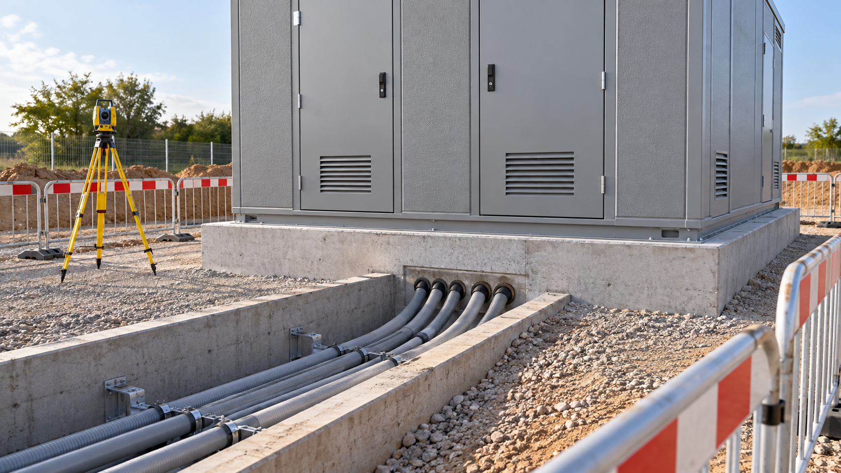
Divide the site into practical work areas with unambiguous boundaries. For each proposed release, identify the approved drawing set, unresolved items outside the boundary and any restrictions that remain inside it. The construction manager should be able to point to the exact area covered. A general “approved with comments” stamp can be misleading if the comments affect the first excavation activity.
Before release, reconcile the combined layout with the current service investigation, equipment interfaces and construction sequence. Confirm that the contractor has the current documents and knows which observations would trigger a stop and reassessment under the approved procedure. Unexpected service indications, different ground conditions or a mismatch in setting-out references need a defined escalation route.
Keep design approval, excavation authorization and inspection acceptance as separate records. They answer different questions. A technically coordinated route may still lack a site permit or access authorization. An excavation completed under the correct permit may still reveal geometry that requires a design change. Combining all three decisions into one signature makes accountability harder to trace.
Where information remains provisional, identify the physical work that must wait. For example, a corridor may be reserved while the final equipment entry remains unresolved. The team can review unaffected work separately, but should not pour a permanent opening around an assumed supplier dimension simply to maintain progress. Document the consequence of waiting alongside the risk of premature construction.
Plan the record package before the route is covered. Specify the surveyed features, the coordinate and level references, photograph locations, inspection points and responsible signatories. A photograph without orientation or a route identifier may be difficult to use later. A surveyed line without its drawing revision may be equally ambiguous.
Record approved deviations as they occur. Link each change to the affected route, drawing and decision record, then update the controlled as-built information. Do not leave a contractor’s marked-up print as the only evidence that a crossing moved. Include enough context for a future maintenance team to understand both the installed location and any restrictions around it.
Earthing connections, duct continuity checks, sealing details and drainage inspections require their own project-specific acceptance criteria. Agree those criteria with the responsible specialists rather than adding generic pass values to a coordination checklist. The coordinator’s role is to make sure the evidence is requested, assigned and available at the right hold point.
Make the record package searchable by physical location as well as by document number. A maintenance engineer may know the affected bay or chamber without knowing the original construction contract. Use consistent asset references across survey files, photographs and inspection reports. Before closing the work package, ask someone outside the installation team to locate one crossing from the records alone. If the route cannot be reconstructed from the supplied evidence, resolve that gap while the installation is still visible and the people who performed the work are available.
Include a deliverable schedule in the enquiry package. It should identify the preliminary data needed for route reservation, the approved data needed for construction and the final records needed for operation. State the date each item is required and the consequences of revisions after that date. This gives bidders a concrete basis for discussing information release instead of promising “drawings after order.”
Use a short responsibility schedule for openings, sleeves, entry seals, cable supports and earthing terminals. Identify who designs, supplies, installs and inspects each item. Check that those assignments agree with the civil and electrical contracts. An interface omitted from both packages becomes a site variation; an interface included differently in both can create incompatible supplied parts.
For substation underground service coordination, Zisheng Electric can review the equipment interfaces associated with transformer and prefabricated substation enquiries. Send the single-line diagram, drawings, equipment data sheets, load list, technical specifications, grid parameters, environmental conditions and installation-site conditions, together with the coordinated route plan and known interface constraints. Our engineering team will review the requirements and respond to project inquiries within 24 hours.

Review the substation fence earthing interface before construction: coordinate gates, security devices, civil changes, inspection records and EPC handover.
View details
Review a substation sump pump specification for hydraulic duty, standby capacity, power loss, level alarms and EPC handover.
View details
Plan a substation water ingress walkdown for EPC handover: inspect roof drainage, thresholds, cable penetrations, trenches and electrical enclosures; assign repairs and release evidence.
View details
Compare transformer bids on a common lifecycle-cost basis. Align guaranteed no-load and load losses, capitalization factors, reference conditions and measurement uncertainty before award, then tie accepted values to the FAT record.
View details