zishengelectric



news
News Center
Providing high-quality power to the world
Search productSearch post
news
Providing high-quality power to the world
Zisheng Electric treats the substation temporary power interface as an engineering boundary, not a construction-site convenience. During an EPC project, lighting, tools, dehumidifiers, oil-processing equipment, control-room HVAC, battery chargers and commissioning instruments may all depend on temporary supplies before the permanent auxiliary system is ready. If ownership, earthing, protection and changeover logic are vague, a small distribution board can create a serious backfeed, nuisance trip or commissioning delay.
A useful temporary-power plan must connect the construction programme to the permanent single-line diagram. It should identify every source, define which loads are permitted at each stage, establish isolation points, and show how the temporary network will be removed without disturbing tested circuits. The objective is not simply to energize equipment. It is to preserve personnel safety, equipment integrity and reliable evidence as the project moves from installation to pre-commissioning and final energization.
Temporary systems change faster than permanent systems. Loads are added, moved or removed as buildings close, transformers are assembled and commissioning teams arrive. A board that was suitable for civil works may be inadequate when vacuum pumps, oil filtration skids and space heaters operate together. At the same time, permanent auxiliary transformers, low-voltage switchboards and DC systems may begin staged testing. The boundary between “temporary” and “permanent” becomes operationally important.
The EPC team should therefore manage temporary power through approved drawings, a controlled load schedule and a named responsible person. This is also the right time to coordinate with the project’s SCADA point-to-point testing plan, because signal tests and control-room work often depend on stable auxiliary supplies. A fluctuating or incorrectly referenced temporary source can create misleading alarms, communication resets and test repetition.
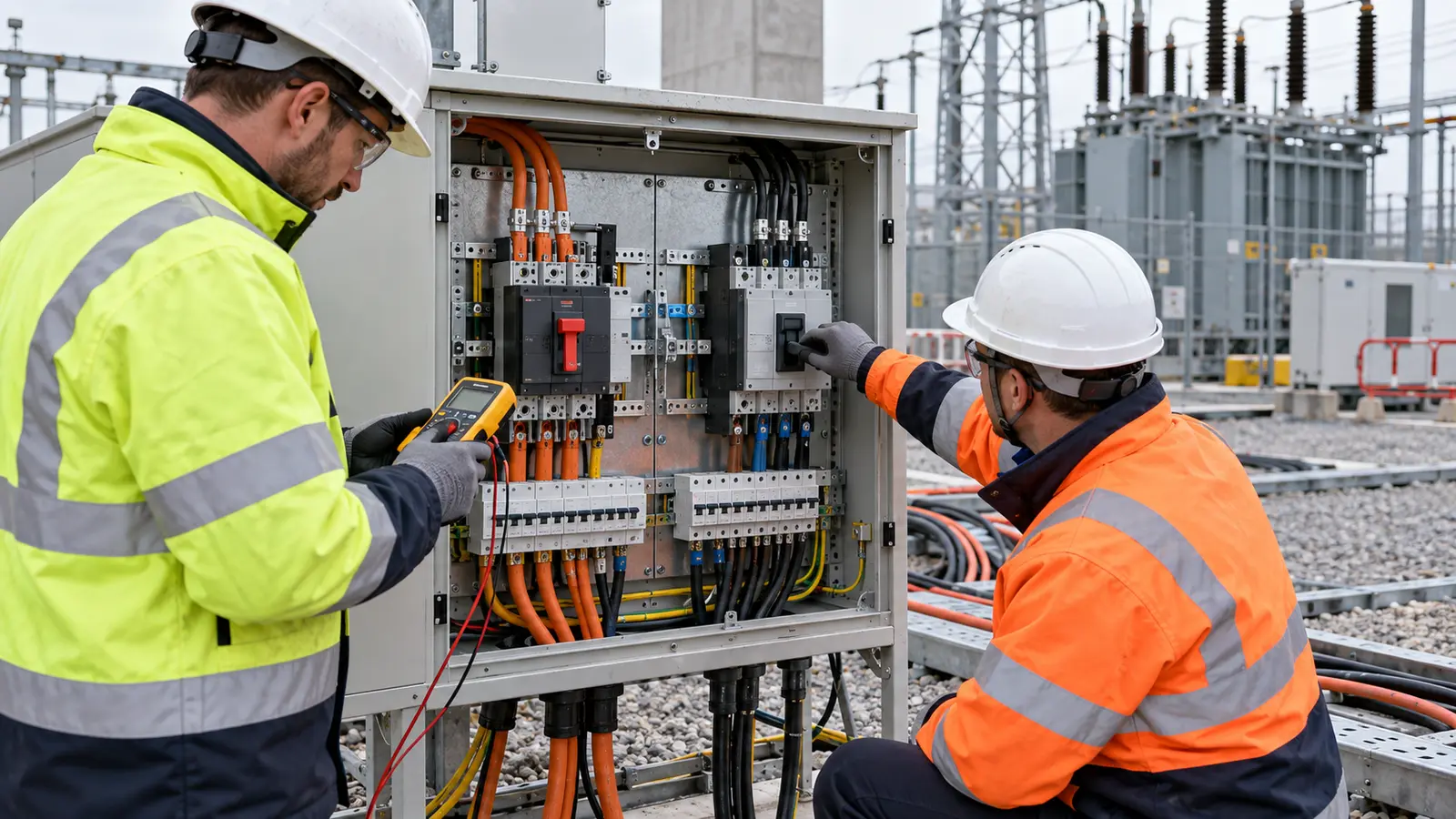
Start with a source register. Record generator ratings, utility construction feeders, temporary transformers and any proposed use of permanent auxiliary transformers. For each source, state voltage, frequency, phase sequence, earthing arrangement, fault level where available, protection device, connection point and responsible owner. Do not assume that two sources can be paralleled or transferred between one another merely because their nominal voltages match.
A single maximum-demand figure is not enough. Separate continuous loads from intermittent tools and high-starting-current equipment. Identify critical preservation loads, including transformer cabinet heaters, control-room environmental systems and battery chargers. Add realistic starting currents and diversity, then map loads to construction milestones. The schedule should reveal when generator capacity, feeder sizes or distribution-board ratings need to change.
For transformer work, the temporary supply may support oil treatment, vacuum pumps and local lighting. These loads must not share an unreviewed circuit with sensitive commissioning instruments. The same principle applies when preparing the first-service thermal survey: test instruments and cooling controls need a defined, stable supply so the resulting temperature record is credible.
| Decision item | Required project input | Engineering check | Release evidence |
|---|---|---|---|
| Source capacity | Time-phased load list, motor starts, ambient derating | Running demand, starting voltage dip, reserve margin | Approved load schedule and calculation |
| Earthing arrangement | Source neutral, site earth grid status, cable CPC data | Fault-return path, touch risk, bonding continuity | Earthing drawing and test record |
| Protection | Prospective fault current, cable ratings, downstream devices | Interrupting duty, discrimination, shock protection | Device schedule and settings record |
| Backfeed prevention | All temporary and permanent sources, transfer points | Mechanical/electrical interlocks and isolation sequence | Approved single-line and witnessed functional test |
| Cable route | Site traffic plan, trenches, lifting routes, drainage | Mechanical protection, separation, bend radius and access | Route inspection photographs and punch closure |
| Changeover | Energization plan, outage window, critical loads | Dead-bus confirmation, phase sequence, load restoration order | Signed switching programme and test sheet |
This table turns a general site service into verifiable engineering decisions. It also supports procurement. The required temporary switchboard, cables and transfer equipment can be specified against calculated duty rather than chosen from whatever is immediately available.
Backfeed is the most important interface hazard. It can occur through temporary jumpers, dual-fed distribution boards, UPS bypasses, generator changeovers, control transformers or incorrectly connected neutral conductors. The single-line diagram should show every possible source and every normally open point. Isolation must be positive, identifiable and suitable for lockout. Labels help, but they are not a substitute for physical interlocking and an approved switching sequence.
Before a permanent auxiliary board is energized, trace all temporary feeders connected to it or to downstream loads. Confirm that no cable can energize an isolated bus from the load side. Where a transfer arrangement is necessary, define whether it is open-transition, manually interlocked or mechanically interlocked. Record phase sequence and neutral treatment on both supplies. The commissioning team should witness the transfer logic with the system in a safe test condition.
The temporary earthing arrangement must reflect the actual source configuration. A generator with a local neutral-earth connection behaves differently from a construction feeder derived from another facility. The project electrical engineer should determine the correct bonding and protective measures for each stage. Earth continuity tests should include temporary flexible cables, distribution boards and metallic enclosures, not only the permanent grid.
Protection settings require the same discipline. Long temporary cables can reduce fault current at the load end, while a powerful source may increase the interrupting duty at the first board. Confirm cable thermal withstand, device breaking capacity and disconnection performance. Where sensitive residual-current protection is used, assess leakage from filters, heaters and long cable runs so normal operation does not produce repeated nuisance trips.
Permanent equipment should remain within its intended duty. If a permanent low-voltage switchgear assembly is used temporarily, document the temporary feeder, incomer protection, cable entries and restoration work. For higher-voltage construction supplies, selection may involve a project-specific 35–46 kV power transformer, but the final choice must follow the actual system study and utility interface.
Temporary cables often cross exactly where the project needs lifting access, trench work and equipment transport. Route planning must therefore use the current logistics plan. Keep cables away from sharp edges, standing water, welding areas and future excavation. Use approved ramps or barriers at traffic crossings, provide strain relief at boards, and maintain access to emergency routes and transformer operating areas.
Separate power cables from protection, communication and instrumentation circuits. The separation requirement depends on voltage, current, shielding and project practice, so it must be stated on the route drawing rather than assumed in the field. Cable identifiers should match the temporary load schedule at both ends. Unused conductors should be safely terminated, and abandoned temporary cables should be removed rather than left as ambiguous site infrastructure.
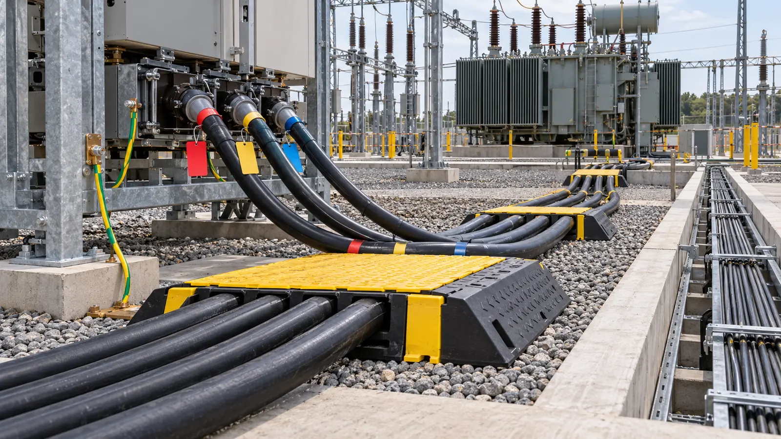
Some temporary loads protect equipment rather than support construction. Transformer cabinet heaters, marshalling-kiosk heaters, breather arrangements, oil-processing equipment and control supplies may need continuous service. Define which loads are critical, how outages will be reported and whether backup supply is required. A preservation log should record extended interruptions and the corrective response.
When transformer auxiliaries are first connected, compare the installed arrangement with the approved schematic. Confirm motor rotation, overload settings, heater supply, local control voltage and cable identification. Coordinate this work with the temperature instrument calibration plan. Stable auxiliary power is necessary if alarm contacts, remote signals and cooling-control functions are to be tested once and accepted.
Changeover is a commissioning activity and should have a written method statement. Identify the required outage, isolation authority, test instruments, phase-sequence check, critical-load restoration order and rollback plan. Before switching, confirm that permanent boards have passed insulation, continuity and functional checks and that protection settings are approved. Do not transfer preservation loads until the permanent source is demonstrably available.
After energization, measure voltage at representative loads, confirm phase sequence, inspect abnormal heating or noise, and test alarms associated with supply failure. Where the permanent network includes medium-voltage distribution, equipment such as 3–10 kV medium-voltage switchgear must be coordinated with the site single-line, protection study and operating procedures. Product ratings alone do not define a safe project interface.
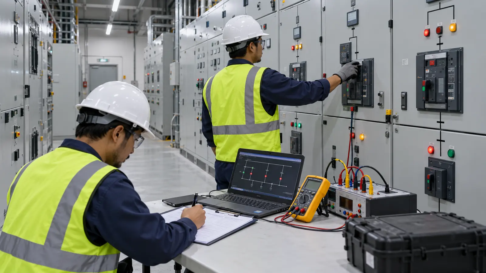
The temporary-power package should include the current single-line diagram, source register, load schedule, cable schedule, earthing arrangement, protection schedule, inspection forms and switching procedures. Each document needs a revision status and named owner. Field changes must be marked and approved before they become the new operating condition.
Useful hold points include initial source energization, first connection to a permanent board, addition of a major load, changeover to permanent auxiliaries and final removal. The EPC manager should define who can authorize each hold point. This approach complements the broader EPC interface review process, where equipment, civil works, access and contractor responsibilities are frozen before execution.
A short operating record gives the temporary system a traceable history. Record the active source, major connected loads, abnormal trips, protection changes, cable relocations and planned outages. The record should distinguish an approved configuration change from a fault response. If a generator is replaced or a new feeder is added, the engineer should update the source register and confirm that protection and earthing assumptions remain valid before the circuit returns to service.
Inspection frequency should follow site conditions and project risk. Heavy rain, excavation, vehicle movements and repeated reconnection justify additional checks. Inspect enclosures, locks, gland plates, cable supports, bonding conductors, route protection and evidence of overheating. Corrective actions need an owner and closure date. A photograph is useful only when it can be linked to a feeder identity, location and inspection record.
Removal deserves the same control as installation. At the end of temporary service, isolate and prove dead, remove jumpers and cables, close unused openings, reinstate barriers, and update the permanent drawings. Inspect any permanent board or cable entry that carried temporary connections. The final release should state that no temporary source, neutral link or bypass remains capable of energizing the completed auxiliary system.
Zisheng Electric can support the transformer and substation equipment interfaces that influence temporary power. Relevant information includes auxiliary voltage and frequency, heater and motor loads, control cabinet diagrams, cooling-system operating sequence, cable-entry requirements and preservation instructions. The EPC team remains responsible for integrating those equipment inputs into the site-wide temporary network and applicable local safety rules.
Early coordination is especially valuable when permanent equipment will be used during construction. It allows the parties to distinguish temporary connections from final wiring, protect warranty boundaries and define the inspections required before restoration. It also reduces the risk that a temporary modification is accidentally carried into handover documentation.
Before accepting the substation temporary power interface, confirm that sources and loads match the approved schedule, cable routes are protected, earthing continuity is recorded, protection devices are correctly rated, and every backfeed path has been eliminated or interlocked. Verify that temporary conductors are identified, critical preservation loads have an outage response, and the permanent-changeover procedure has named authorities and evidence requirements.
For project review, send Zisheng Electric the drawings, data sheets, load list, technical specification, single-line diagram, grid parameters, environmental conditions and installation-site conditions. We can relate those inputs to applicable transformer, switchgear and auxiliary-equipment interfaces and identify points that require EPC confirmation. Our engineering team will review the requirements and respond to project inquiries within 24 hours.
Build a transformer protection interface matrix covering CTs, relays, trips, alarms, SCADA, auxiliary power, FAT and commissioning responsibilities.
View details
Plan substation arc flash study inputs for EPC projects: source fault data, transformer impedance, switchgear geometry, protection settings and as-left handover.
View details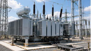
Define transformer auxiliary power for EPC projects: AC/DC supplies, cooling controls, cabinet heaters, cable boundaries and FAT acceptance checks.
View details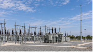
Substation lightning mast interface guide for EPC teams: coordinate the risk basis, protected volumes, foundations, earth bonds, services and acceptance records.
View details