zishengelectric






Project Partners
Phone/WhatsApp: 8619131285373
Email: info@zishengtransformer.com
Factory Headquarters: No. 118, Jingyi Street, Economic Development Zone.
Search productSearch post
Project Partners
Phone/WhatsApp: 8619131285373
Email: info@zishengtransformer.com
Factory Headquarters: No. 118, Jingyi Street, Economic Development Zone.
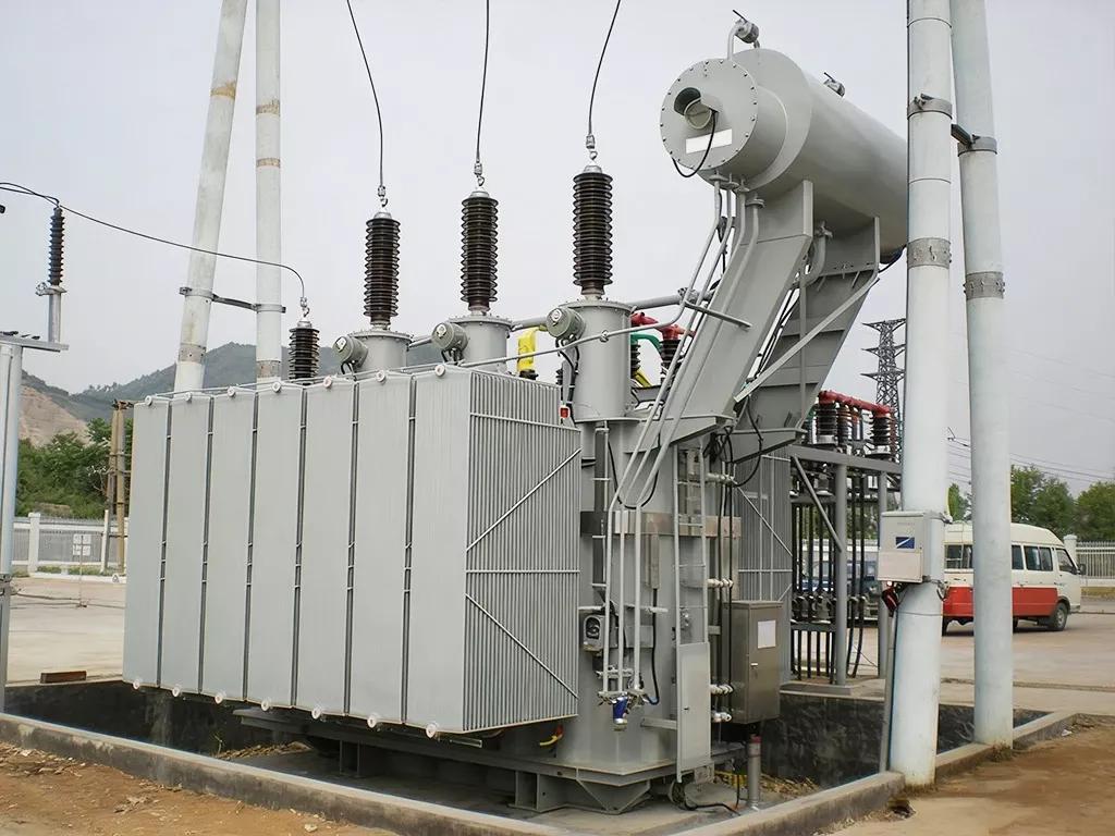
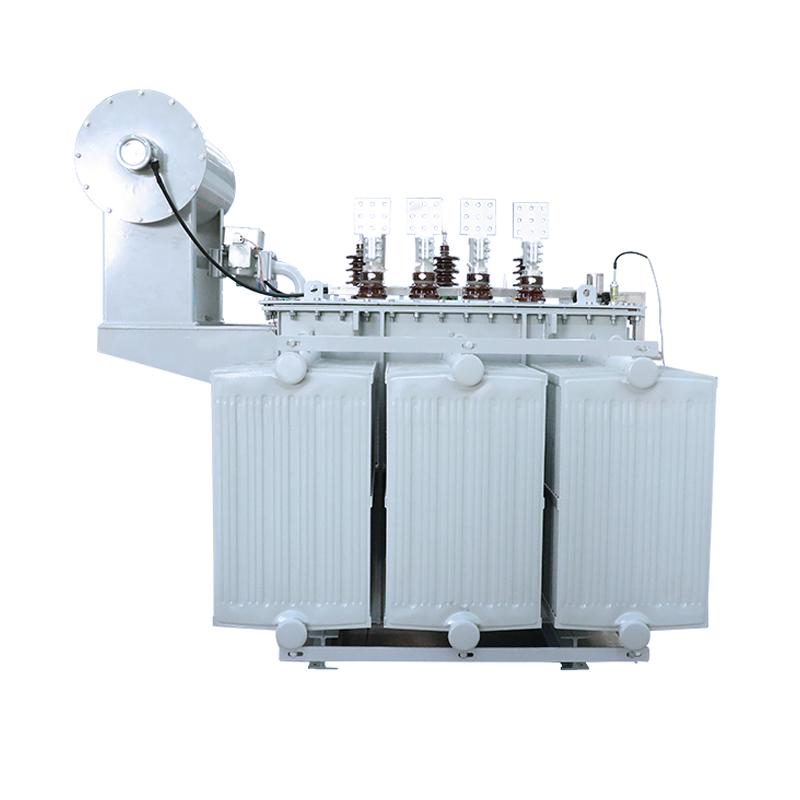
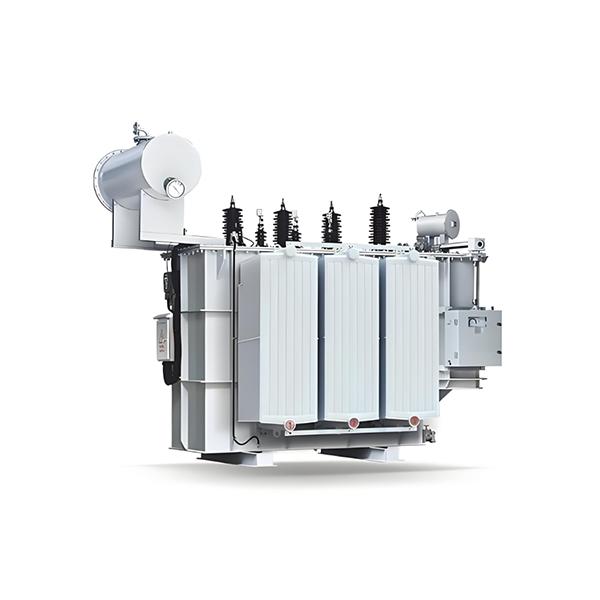
ZISHENG 35kV–46kV Power Transformers are designed for reliable voltage transformation in power transmission, distribution, industrial, mining, renewable energy, and utility applications. The transformers can be engineered according to project requirements, including capacity, voltage level, cooling method, insulation level, winding material, tap-changing system, and protection configuration.
The 35kV–46kV Power Transformer uses optimized core and winding designs to reduce no-load and load losses while maintaining stable operation under demanding electrical conditions. High-quality insulating materials and a robust tank structure provide reliable insulation and mechanical protection.
The transformer can be customized for different grid voltage levels, power capacities, environmental conditions, installation methods, and project standards. This makes it suitable for medium- and high-voltage substations, industrial power systems, renewable energy projects, and utility distribution networks.
ZISHENG applies process control from raw-material selection and component manufacturing through assembly and final testing. Each transformer is subject to performance and electrical tests before shipment to ensure compliance with the agreed technical specifications.
All technical parameters can be customized according to the project requirements, including:
The technical data above is for reference only. ZISHENG provides project-specific transformer designs based on the customer's grid conditions, installation environment, operating requirements, and applicable standards.
| Item | Technical Specification |
|---|---|
| Product Type | Oil-Immersed Power Transformer |
| Rated Capacity | 1,000–63,000 kVA |
| Rated Frequency | 50 / 60 Hz |
| Number of Phases | 3 Phase |
| Installation | Outdoor / Indoor |
| Cooling Method | ONAN / ONAF |
| Insulation Medium | Transformer Oil |
| Core Material | High-permeability Grain-Oriented Silicon Steel |
| Winding Material | Copper / Aluminum |
| HV Rated Voltage | 35 kV / 38.5 kV / 40.5 kV / 46 kV |
| LV Rated Voltage | 0.4 kV / 6.3 kV / 10.5 kV / 11 kV / 13.8 kV |
| Tap Range | ±2 × 2.5% / ±5% / Customized |
| Tap Changer | Off-Circuit Tap Changer / OLTC |
| Vector Group | Dyn11 / YNd11 / Customized |
| Neutral | Neutral Bushing Available |
| Impedance Voltage | Typically 6–12% / Customized |
| No-Load Loss | According to IEC / Project Requirements |
| Load Loss | According to IEC / Project Requirements |
| Temperature Rise | According to IEC 60076 |
| Noise Level | According to IEC / Project Requirements |
| Service Life | ≥30 Years under Normal Operating Conditions |
| Applicable Standard | IEC 60076 / IEEE C57 / ANSI / Customer Specification |
| Item | Specification |
|---|---|
| Rated Voltage | 35 kV / 46 kV |
| Maximum System Voltage | Project Dependent |
| Power Frequency Withstand | According to Insulation Class |
| Lightning Impulse Withstand | According to IEC 60076 / Project Requirements |
| Partial Discharge | According to Applicable Standard |
| Short-Circuit Withstand | According to IEC 60076 |
| Insulation Class | Oil-Immersed |
| Frequency | 50 / 60 Hz |
| Phase Sequence | ABC |
| Polarity | According to Vector Group |
| Voltage Regulation | Project Dependent |
| Efficiency | ≥98% depending on capacity and design |
| Power Factor | Project / Grid Dependent |
High-Voltage Winding
Low-Voltage Winding
| Item | Specification |
|---|---|
| Insulating Oil | Mineral Oil / Natural Ester / Customized |
| Main Insulation | Oil-Paper Insulation System |
| Insulation Structure | High-Voltage / Low-Voltage / Core Insulation |
| Drying Process | Vacuum Drying |
| Oil Treatment | Vacuum Oil Filtration |
| Insulation Level | Project Specific |
| Partial Discharge | Controlled according to applicable standard |
Depending on transformer capacity:
ONAN — Oil Natural Air Natural
ONAF — Oil Natural Air Forced
Optional:
Off-Circuit Tap Changer
Typical configuration:
On-Load Tap Changer — OLTC
Available for applications requiring voltage regulation under load.
Optional features:
Depending on transformer design and capacity:
Optional monitoring and protection systems include:
Each transformer can undergo comprehensive factory testing before shipment.
Routine Tests
Type / Special Tests
According to project requirements:
Primary Standard
Depending on the target market, the transformer can also be designed according to:
35kV / 46kV power transformers are suitable for:
Our 35kV / 46kV Power Transformers can be engineered and manufactured according to specific grid conditions, project requirements and applicable international standards.
| Customization Item | Available Options |
|---|---|
| Rated Capacity | 1 MVA – 63 MVA+ |
| High Voltage | 35 kV / 38.5 kV / 40.5 kV / 46 kV |
| Low Voltage | 0.4 kV / 6.3 kV / 10.5 kV / 11 kV / 13.8 kV / Customized |
| Frequency | 50 Hz / 60 Hz |
| Phase | Three Phase |
| Voltage Ratio | Customized according to project requirements |
| Impedance Voltage | Customized |
| No-Load Loss | Optimized according to efficiency requirements |
| Load Loss | Optimized according to project requirements |
| Insulation Level | Customized according to system voltage and applicable standards |
| Lightning Impulse Level | Customized |
| Short-Circuit Withstand | Designed according to IEC / IEEE requirements |
Off-Circuit Tap Changer
On-Load Tap Changer — OLTC
Customers can select the cooling configuration according to transformer capacity and operating conditions:
| Item | Customization |
|---|---|
| Transformer Oil | Mineral Oil / Natural Ester / Customized |
| Insulation System | Oil-Paper Insulation |
| Insulation Level | Project Specific |
| Insulation Coordination | Customized |
| Partial Discharge Requirement | Project Specific |
| Vacuum Drying | Available |
| Oil Treatment | Vacuum Filtration / Degassing |
| Sealing System | Conventional / Fully Sealed |
The transformer tank can be customized according to transportation, installation and environmental requirements.
Available configurations include:
Optional protection and monitoring systems:
The transformer can be engineered for different operating environments:
Hot & Humid Areas
Desert Areas
Coastal / Marine Areas
High-Altitude Areas
Cold Climate
Optional surface-treatment systems:
The transformer can be manufactured according to:
Customized documentation can include:
For EPC and utility projects, we can customize the transformer based on:
Grid Requirements → Electrical Parameters → Insulation Level → Cooling → Protection → Environmental Conditions → Applicable Standards → Transportation → Installation
Engineered to Your Project. Manufactured to Your Specification.
Our 35kV / 46kV Power Transformers are professionally packed and prepared for international transportation, with packaging methods selected according to transformer capacity, dimensions, weight, destination, transportation mode and project requirements.
Each transformer is inspected and properly protected before shipment.
Before packing, key transformer components are protected against damage during transportation.
Depending on transformer design and transportation requirements, we provide:
Oil-Filled Shipment
Oil-Drained Shipment
Oil-Filled / Nitrogen-Protected Shipment
Transformer accessories can be packed separately to reduce transportation risk.
Typical separately packed items include:
Each package can be clearly marked with:
Part Name → Quantity → Package No. → Gross Weight → Net Weight → Dimensions → Installation Reference
Smaller accessories and sensitive components can be packed in reinforced export wooden cases.
Suitable for:
The wooden cases can be reinforced for container and international sea transportation.
For heavy or large components, reinforced steel-frame packing can be provided.
Advantages:
For long-distance international shipments, additional protection can include:
Special protection can be provided for tropical, coastal, humid, desert and long-term storage environments.
We support multiple international transportation methods:
| Shipping Method | Application |
|---|---|
| FCL Container | Suitable for small and medium transformers |
| Open Top Container | Suitable for oversized/heavy equipment |
| Flat Rack Container | Suitable for large transformer bodies |
| Break Bulk | Suitable for large power transformers |
| Ro-Ro | Suitable for certain heavy equipment |
| Road Transportation | Factory → Port / Project Site |
| Rail Transportation | Suitable for specific international routes |
For large transformers, the transportation solution is designed according to the overall dimensions, axle load, lifting points, center of gravity and destination infrastructure.
Professional loading procedures help minimize transportation risks.
Each package can be marked with:
Before shipment, our logistics team verifies:
Transformer Dimensions → Package Dimensions → Container Type → Loading Method → Weight Distribution → Lashing → Clearance → Shipping Documents
For oversized transformers, we can coordinate special transportation solutions based on the destination port and project site requirements.
A complete shipping document package can include:
Additional documents can be provided according to EPC, utility or destination-country requirements.
For EPC and large-scale power projects, shipping can be coordinated according to the project schedule:
Factory Testing → Final Inspection → Packing → Loading → Port Transportation → Sea Freight → Customs Clearance → Destination Port → Site Delivery
We can also provide technical documentation and packing information required for customs clearance, site handling and installation.
Shipping arrangements can be customized based on:
Every 35kV / 46kV Power Transformer undergoes strict factory inspection and testing before shipment. Testing is performed according to IEC 60076, applicable IEEE/ANSI standards, and customer-specific technical requirements.
All critical raw materials and components are inspected before entering production.
| Material / Component | Inspection Items |
|---|---|
| Silicon Steel Core | Material grade, thickness, magnetic properties |
| Copper / Aluminum Conductor | Material, dimensions, conductivity |
| Insulation Paper | Thickness, insulation properties, moisture |
| Transformer Oil | Breakdown voltage, moisture, dielectric properties |
| Bushings | Rated voltage, insulation level, appearance |
| Steel Tank | Material, dimensions, welding quality |
| Sealing Components | Material, dimensions, oil resistance |
| Accessories | Specification, performance, appearance |
Critical materials can be supplied with material certificates and inspection records according to project requirements.
Quality control is implemented throughout the manufacturing process.
Routine tests are performed on each completed transformer before delivery.
The resistance of each winding is measured to verify:
Test results are compared between phases and recorded in the factory test report.
The transformation ratio is measured at all applicable tap positions.
The test verifies:
The vector group is verified according to the specified design, such as:
The transformer is energized under rated voltage and the following parameters are measured:
This test verifies the performance of the magnetic core.
The transformer is tested under specified conditions to determine:
Results are evaluated against the specified technical requirements.
For 35kV / 46kV transformers, insulation performance is critical.
Factory dielectric testing may include:
Checks the insulation capability between:
Verifies the insulation between turns, layers and windings under elevated frequency/voltage conditions.
For applicable transformer designs, impulse testing verifies the ability of the insulation system to withstand transient overvoltage caused by lightning or switching events.
Insulation resistance is measured between:
The test helps evaluate:
Insulating oil is tested before filling and, where applicable, after final filling.
Typical tests include:
Oil treatment is performed through vacuum filtration, dehydration and degassing when required by the transformer design.
The transformer tank and sealing system undergo pressure/vacuum and leakage inspections according to the applicable design and standard.
Inspection includes:
No visible oil leakage is permitted before shipment.
For applicable high-voltage transformer designs, partial discharge testing can be performed according to the relevant standard and customer specification.
The test helps identify potential:
For projects requiring enhanced insulation performance, a specified partial discharge acceptance level can be agreed during technical clarification.
For type-tested or specially specified transformers, temperature rise testing verifies the thermal performance of:
The results confirm that operating temperatures remain within the specified limits.
Before shipment, the transformer is inspected for:
All installed protection and monitoring devices can be function-tested.
For transformers equipped with an On-Load Tap Changer:
Depending on project requirements, additional tests can be provided:
| Test | Purpose |
|---|---|
| Temperature Rise Test | Verify thermal performance |
| Lightning Impulse Test | Verify impulse insulation strength |
| Short-Circuit Test | Verify mechanical/electrical withstand capability |
| Partial Discharge Test | Evaluate insulation quality |
| Noise Level Test | Verify acoustic performance |
| Zero-Sequence Impedance Test | Verify system characteristics |
| SFRA Test | Assess winding/core mechanical condition |
| Tan Delta Test | Evaluate insulation condition |
| DGA Test | Assess transformer oil and internal condition |
Special testing is normally confirmed during the technical specification and contract stage.
Before loading, our QC team performs a final inspection covering:
Electrical Performance → Mechanical Condition → Accessories → Oil Level → Leakage → Painting → Nameplate → Packing → Shipping Marks
The transformer is released for shipment only after the required inspection and testing procedures are completed.
A complete Factory Routine Test Report can be provided for each transformer.
Typical information includes:
For EPC, utility and large-scale projects, Factory Acceptance Test (FAT) can be arranged.
Customers or third-party inspectors may witness selected tests, including:
The exact FAT procedure is agreed according to the approved technical specification and Inspection & Test Plan (ITP).
All 35kV / 46kV Power Transformers undergo routine factory testing before delivery. Each test is performed according to the applicable requirements of IEC 60076, IEEE/ANSI standards, and the approved project technical specification.
Routine testing is used to verify the transformer's electrical performance, insulation integrity, winding condition, loss characteristics, mechanical condition and operational reliability.
The DC resistance of each winding is measured at the specified temperature.
Testing includes:
Purpose:
The transformer turns ratio is measured between the HV and LV windings.
Testing includes:
Purpose:
The measured ratio must comply with the specified tolerance in the applicable standard.
The phase relationship between HV and LV windings is verified.
Typical configurations include:
Purpose:
The transformer is energized at the specified rated voltage and frequency with the secondary winding open.
The following parameters are measured:
Purpose:
No-load loss is primarily associated with the transformer core.
Load loss is measured under the specified test conditions.
The test evaluates:
Purpose:
The transformer short-circuit impedance is measured according to the applicable test procedure.
The test determines:
Purpose:
An AC test voltage is applied between specified windings and earth for the required test duration.
Typical insulation paths include:
HV → Earth
LV → Earth
HV → LV
The exact test voltage and duration depend on the transformer's insulation level and applicable standard.
Purpose:
An elevated-frequency voltage is applied to the transformer windings to verify inter-turn and inter-layer insulation.
The test evaluates:
Purpose:
To verify that the internal insulation system can withstand the specified electrical stresses during operation.
Insulation resistance is measured between the principal electrical circuits.
Typical measurements include:
Where applicable, the test can include:
Purpose:
For oil-immersed transformers, insulating oil is inspected and tested according to the applicable requirements.
Typical parameters include:
Purpose:
The transformer tank, radiators, valves and sealing system are inspected for oil leakage.
Inspection areas include:
Acceptance: No unacceptable oil leakage is permitted.
For transformers equipped with a tap changer, operation is verified before shipment.
Testing includes:
Additional checks may include:
HV, LV and neutral bushings are inspected before delivery.
Inspection includes:
For condenser bushings, additional electrical tests can be performed according to the applicable specification.
Installed protection and monitoring devices are checked for correct operation.
Typical devices include:
The actual test scope depends on the transformer configuration.
For transformers equipped with forced cooling, the cooling system is function-tested.
Testing can include:
For ONAF/OFAF/ODAF systems, the cooling equipment is verified according to the approved design.
The auxiliary electrical system is checked before shipment.
Testing includes:
The transformer grounding system is inspected to ensure reliable electrical continuity.
Inspection includes:
Before shipment, the nameplate information is checked against the approved technical documentation.
Typical information includes:
The completed transformer is inspected before release.
After completion of testing, a Factory Routine Test Report can be provided for each transformer.
The report may include:
| Test | Recorded Result |
|---|---|
| Winding Resistance | Measured Value |
| Voltage Ratio | Measured Value |
| Vector Group | Confirmed |
| No-Load Loss | Measured Value |
| No-Load Current | Measured Value |
| Load Loss | Measured Value |
| Impedance Voltage | Measured Value |
| Applied Voltage Test | Pass |
| Induced Voltage Test | Pass |
| Insulation Resistance | Measured Value |
| Oil Test | Test Results |
| Leakage Test | Pass |
| Tap Changer Test | Pass |
| Protection Test | Pass |
| Cooling System Test | Pass |
| Final Inspection | Pass |
Incoming Material Inspection
↓
Core & Winding Inspection
↓
Transformer Assembly
↓
Winding Resistance & Ratio Test
↓
No-Load & Load Loss Test
↓
Impedance Test
↓
Applied & Induced Voltage Test
↓
Insulation & Oil Inspection
↓
Accessory & Protection Test
↓
Leakage & Final Inspection
↓
Factory Test Report
↓
Packing & Shipment
Routine Testing — 100% Factory Tested
Electrical Tests
Winding Resistance • Voltage Ratio • Vector Group • No-Load Loss • Load Loss • ImpedanceInsulation Tests
Applied Voltage • Induced Voltage • Insulation ResistanceFunctional Tests
Tap Changer • Cooling System • Protection Devices • Control CircuitsFinal Inspection
Oil Quality • Leakage • Grounding • Accessories • NameplateStandard: IEC 60076 / IEEE / ANSI / Project Specifications
Test Report: Supplied with Each Transformer
The 35kV / 46kV Power Transformer is designed for medium- and high-voltage power transmission and distribution systems where reliable voltage transformation, efficient power delivery, and long-term operation are required. It can be engineered for utility, industrial, renewable-energy and infrastructure projects according to specific grid and environmental conditions.
35kV / 46kV power transformers are widely used in utility substations to transform power between transmission, sub-transmission and distribution voltage levels.
Typical applications:
Typical functions:
High-Voltage Grid → 35/46kV → Medium/Low-Voltage Distribution
The transformer can be customized according to the utility's voltage, capacity, impedance, insulation and protection requirements.
Large industrial facilities require stable and reliable electrical power for continuous production.
The transformer can be used in:
Utility Grid → 35/46kV Transformer → Plant Distribution System → Industrial Loads
Customized designs can accommodate high starting currents, fluctuating loads, continuous operation and specific harmonic or voltage requirements.
Mining operations often require high-capacity power systems in remote and harsh environments.
Applications include:
The transformer can be designed for:
35kV / 46kV transformers can provide power for large oil and gas facilities.
Typical applications include:
Special engineering can be provided for:
The transformer can be used as part of utility-scale photovoltaic power generation systems.
PV Modules → Inverter → Step-Up Transformer → 35/46kV Collection Grid → Substation → Utility Grid
Applications include:
Transformer configurations can be customized according to:
35kV / 46kV transformers can be integrated into wind-farm collection and grid connection systems.
Typical application:
Wind Turbine → Step-Up Transformer → 35/46kV Collector System → Main Substation → Grid
Suitable for:
Design considerations may include:
The transformer can be used in hydropower generation and transmission systems.
Applications include:
Typical configuration:
Generator → Generator Transformer → 35/46kV Grid → Transmission Network
Large data centers require high-reliability electrical infrastructure.
35kV / 46kV transformers can be used for:
Design considerations can include:
The transformer can provide power for major infrastructure developments.
Applications include:
The transformer can be integrated into centralized or distributed power-distribution systems.
For large petrochemical complexes, transformers can supply multiple medium-voltage distribution sections.
Typical system:
Utility Incoming Supply → 35/46kV Transformer → MV Switchgear → Plant Distribution
Suitable for:
Customized protection, monitoring and corrosion-resistant construction can be specified according to project conditions.
35kV / 46kV transformers can serve centralized power distribution for large industrial and commercial developments.
Applications include:
Typical configuration:
Utility Grid → 35/46kV Substation → MV Distribution → Individual Buildings / Factories
For developing power networks, the transformer can be used to expand medium-voltage electricity distribution.
Applications include:
The design can be adapted to local grid standards and environmental conditions.
The transformer can support hybrid power systems combining conventional and renewable generation.
For example:
Solar Farm + Battery Storage + Mining Load
or
Wind Farm + Solar Farm + Industrial Load
The transformer provides the necessary voltage transformation and grid interface for the project.
35kV / 46kV transformers can be used in utility-scale BESS projects.
Typical configuration:
Battery System → PCS → Step-Up Transformer → 35/46kV Collection System → Grid
Important design considerations include:
For large generation projects, the transformer can serve as the interface between the generation facility and the utility network.
Typical applications:
The transformer can be engineered according to the utility's grid-connection study and interconnection requirements.
The transformer can be customized for different operating environments.
Suitable for:
Design options include enhanced cooling, moisture protection and corrosion-resistant coatings.
Suitable for:
Possible design considerations:
Possible requirements:
Design can be adjusted for:
46kV Grid
↓
35/46kV Power Transformer
↓
11kV / 10.5kV / 6.3kV Distribution
↓
Industrial / Commercial Loads
Solar / Wind Generation
↓
LV / MV Output
↓
35/46kV Step-Up Transformer
↓
Grid Connection
Utility Grid
↓
35/46kV Transformer
↓
MV Switchgear
↓
Factory Distribution Network
The 35kV / 46kV Power Transformer is suitable for:
Utility Projects
Grid Substations • Distribution Networks • Electrification
Industrial Projects
Mining • Steel • Cement • Chemical • Manufacturing
Energy Projects
Solar • Wind • Hydropower • BESS • Hybrid Energy
Infrastructure Projects
Railways • Airports • Ports • Hospitals • Data Centers
EPC Projects
Turnkey Substations • Power Distribution • Grid Connection Projects
For EPC and utility projects, transformer design can be developed according to:
Grid Voltage → Load Profile → Capacity → Insulation Level → Short-Circuit Level → Cooling → Protection → Environment → Applicable Standard → Transportation & Installation
From Grid Connection to Industrial Power Distribution — Engineered for Your Project.
A 35kV / 46kV Power Transformer is an oil-immersed transformer designed for high-voltage power transmission, sub-transmission and distribution systems. It can be used for utility substations, industrial facilities, mining projects, renewable-energy plants and large infrastructure projects.
The transformer can be manufactured from approximately 1 MVA to 63 MVA or higher, depending on the application.
Common capacities include:
Larger capacities can be engineered according to project requirements.
Typical high-voltage configurations include:
The exact rated voltage and maximum system voltage are selected according to the customer's grid specifications.
The LV side can be customized, including:
Yes. The transformer can be designed for 50Hz or 60Hz operation according to the destination country's power-grid requirements.
Yes. The transformer is engineered according to project requirements.
Customization can include:
Depending on transformer capacity and application, available cooling methods include:
The cooling system is selected based on capacity, ambient temperature and project operating conditions.
Yes. The transformer can be engineered for high-ambient-temperature applications such as Middle East, Africa, South Asia and tropical regions.
Design considerations may include:
The required ambient temperature should be specified during technical design.
Yes. 35kV / 46kV transformers are suitable for mining and mineral-processing projects, including:
The transformer can be customized for high loads, dusty environments, high altitude and demanding operating conditions.
Yes. It can be used as a step-up or step-down transformer in renewable-energy systems.
Typical applications include:
Solar/Wind Generation → Transformer → 35/46kV Collection Grid → Substation → Utility Grid
The transformer can be designed according to inverter output, collection voltage, capacity, harmonic characteristics and grid-connection requirements.
The transformer can be manufactured according to applicable international and regional standards, including:
The applicable standard should be confirmed before production.
Each transformer undergoes applicable factory routine tests before delivery.
Typical tests include:
A Factory Routine Test Report can be provided.
Yes. For EPC, utility and large projects, Factory Acceptance Testing (FAT) can be arranged according to the approved Inspection & Test Plan (ITP).
Customer or third-party inspectors can witness agreed testing and inspection activities before shipment.
Depending on the transformer configuration, options include:
Yes. An On-Load Tap Changer (OLTC) can be provided when voltage regulation under load is required.
Options can include:
Off-circuit tap changers are also available.
The standard configuration can use high-quality mineral insulating oil.
Other options, such as natural ester fluid, can be considered according to project requirements and environmental objectives.
The transformer is prepared according to its size, weight, transportation method and destination.
Available packing and shipping solutions include:
Large transformers can be shipped with selected accessories packed separately.
Yes. Depending on project requirements, the documentation package can include:
Yes. We can review customer-provided Technical Specifications, Single-Line Diagrams, Data Sheets and Utility Requirements and develop the transformer design accordingly.
To prepare an accurate technical and commercial quotation, please provide:
For EPC projects, a single-line diagram or technical specification is highly recommended.
When properly designed, installed, operated and maintained, an oil-immersed power transformer can provide 30 years or more of service. Actual service life depends on loading, temperature, insulation condition, maintenance and operating environment.
Yes. We support OEM and project-based customized manufacturing, including electrical parameters, mechanical configuration, nameplate, documentation, accessories and applicable standards.
Send us your required capacity, HV/LV voltage, frequency, quantity, destination and technical specification. Our engineering team can review the requirements and provide a customized technical proposal and quotation.
Need a 35kV / 46kV Transformer for Your Project?
Send Your Technical Specification → Get a Customized Solution & Quote
35kV 46kV Power Transformer