zishengelectric





news
News Center
Providing high-quality power to the world
Search productSearch post
news
Providing high-quality power to the world
A transformer bushing specification is an interface document, not a catalogue selection copied into a transformer data sheet. The bushing must carry rated and fault current, withstand the transformer insulation level, survive the real site environment, connect correctly to conductors and current transformers, and remain accessible for inspection throughout the asset life. For EPC teams, those requirements connect the transformer supplier with the substation layout, protection, civil, conductor, testing and commissioning disciplines.
This guide explains how to define and review transformer bushings for IEC-aligned substation projects. It is intended for owners, consultants, EPC contractors and procurement teams preparing a technical enquiry or approving supplier documents. Project voltage, earthing, altitude, pollution severity, seismic duty and utility rules must always be confirmed; no single bushing arrangement is universal.
A bushing passes an energized conductor through the grounded transformer tank or cover. That simple description hides several coordinated decisions: terminal insulation level, rated current, short-time current, dielectric test duty, external creepage distance, internal oil-side geometry, flange dimensions, conductor connection, current-transformer accommodation, mechanical loading and transport arrangement.
If the transformer supplier selects the bushing without confirmed substation information, late changes can affect the tank cover, cable or bus layout, support steel, clearances and protection wiring. If the EPC team specifies only system voltage and current, the manufacturer may have insufficient information to evaluate pollution, altitude, terminal forces or CT interfaces. The specification should therefore define required performance while assigning each interface to a named drawing or schedule.
| Decision item | Project input | Supplier evidence | Typical release risk |
|---|---|---|---|
| Electrical rating | Highest system voltage, insulation level, rated and fault current | Bushing data sheet and test basis | Insulation or thermal mismatch |
| Site environment | Altitude, pollution, humidity, salt, temperature and solar exposure | External insulation selection and material declaration | Flashover or accelerated ageing |
| Terminal connection | Bus, flexible conductor or cable interface and terminal forces | Terminal drawing, hardware and permissible loads | Site rework or damaged sealing system |
| Bushing CTs | Protection and metering cores, ratios, classes and burdens | CT schedule, terminal diagram and test records | Incorrect protection or untraceable secondary circuits |
| Physical interface | Phase spacing, orientation, clearances and access | Approved general arrangement and section drawing | Air-clearance conflict or inaccessible test tap |
| FAT and shipment | Witness points, inspection records and preservation | Approved ITP, routine records and packing plan | Unverified equipment or transport damage |
For many IEC projects, IEC 60137 is the principal product standard for insulated bushings above 1 kV. The transformer insulation coordination and dielectric test requirements also connect to IEC 60076-3. Pollution selection may require the IEC TS 60815 series or a utility-specific method. Bushing current transformers should be coordinated with the applicable parts of IEC 61869 and the project protection specification.
The enquiry should identify editions and the project document hierarchy. A statement such as “IEC compliant” is incomplete when the utility specification applies different test levels, terminal forces or pollution assumptions. Record deviations explicitly and close them before the transformer design is frozen. The same discipline is described in our guide to transformer datasheet approval for EPC projects.
Specify the highest voltage for equipment, rated frequency, rated current, insulation levels and required dielectric tests. System nominal voltage alone is not enough. The bushing insulation must be coordinated with the transformer terminal and the project insulation scheme, including lightning impulse, switching impulse where applicable, power-frequency withstand and the surrounding air clearances.
Rated current should reflect the transformer terminal current at the relevant cooling stage and any approved overload duty. The supplier should state the thermal basis, connection details and temperature limitations. Short-time current duty must be compatible with the transformer and system study. Where a neutral bushing carries a different continuous or fault duty from phase bushings, specify it separately rather than assuming an identical rating.
Capacitance-graded bushings may include test taps or voltage taps. The purpose, normal operating condition, protective cap, earthing arrangement and access requirement should appear on drawings and operating instructions. A test tap left ungrounded or inaccessible is an avoidable commissioning and maintenance risk.
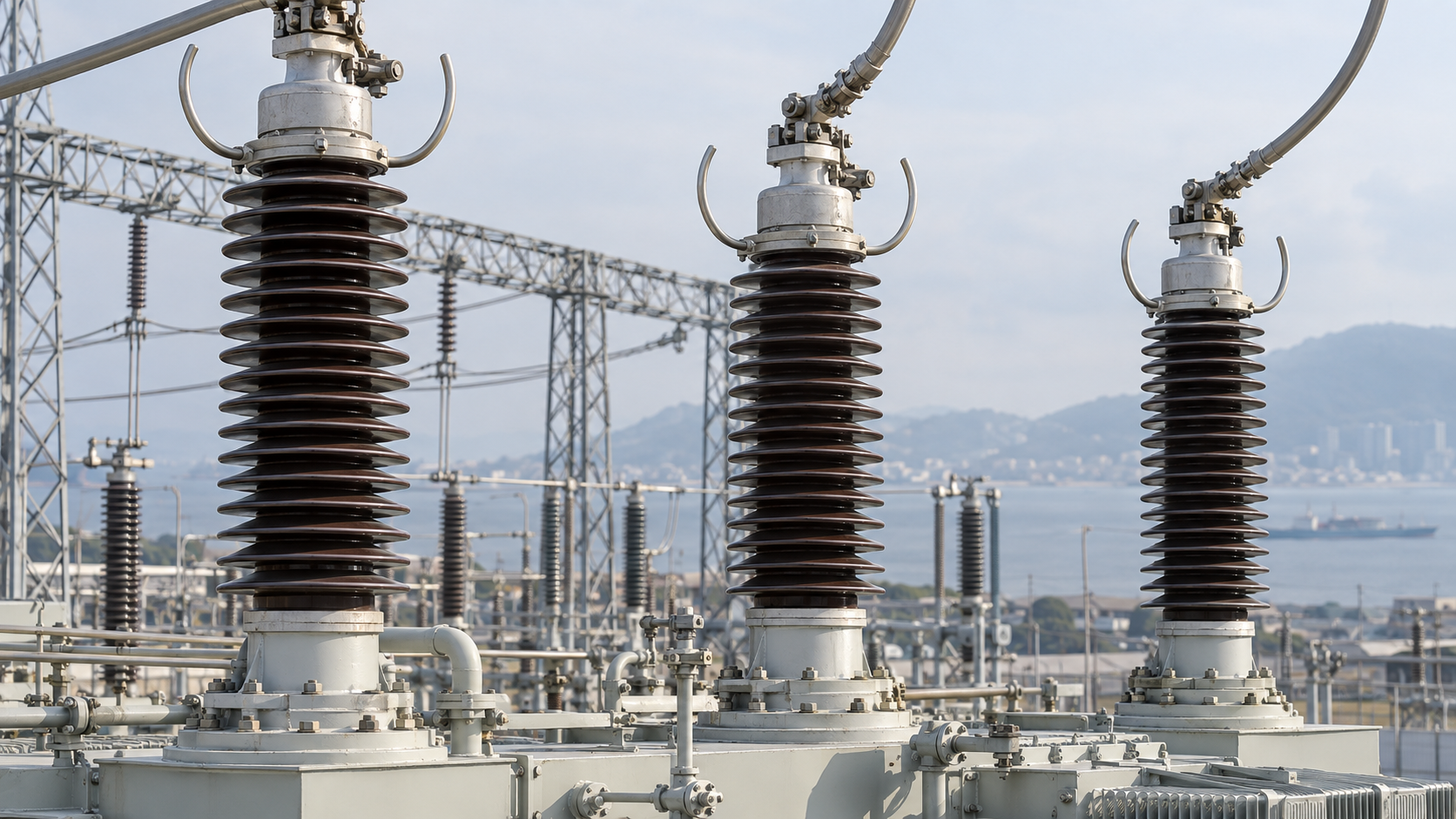
External insulation selection should start with a documented site-pollution assessment. Coastal salt, industrial emissions, desert dust, seasonal fog and limited washing access produce different contamination profiles. A generic creepage value cannot replace project evaluation, and creepage distance should not be selected only by copying a previous project in another climate.
The specification should record site pollution severity, altitude, rainfall or washing assumptions, orientation and maintenance strategy. Porcelain and composite housings have different handling, contamination and damage considerations. The purchaser should request the material, shed profile, total creepage distance, protected creepage where relevant and evidence supporting the proposed selection.
Altitude affects external insulation performance and must be coordinated with the transformer design and substation clearances. If the site elevation exceeds the standard reference conditions used by the design, the supplier and EPC insulation-coordination engineer should document the correction approach. Clearances shown on the general arrangement must be checked against nearby structures, conductors, surge arresters and transport constraints.
The bushing terminal is where transformer design meets the substation conductor system. Define whether the connection uses flexible conductors, rigid bus, cable box equipment or another arrangement. Provide conductor size, direction, hardware, expected static loads and credible short-circuit forces. The transformer supplier should confirm permissible terminal loads and any restriction on pulling, torsion or cantilever loading.
Phase spacing and terminal elevation should be reviewed in the three-dimensional substation context. A dimensionally correct transformer drawing can still conflict with gantries, cable trenches, fire walls or access routes. The approved general arrangement should show bushing orientation, phase identification, terminal height, minimum clearances and removable components.
For transport, determine whether bushings ship installed or separately. Large bushings often require removal, dedicated crates, oil-side protection, humidity control and documented reinstallation procedures. Lifting devices, flange gaskets, fastener torque and cleanliness controls should be included in the site method statement.
Bushing current transformers are frequently specified for differential, restricted-earth-fault, overcurrent, metering or monitoring functions. The protection engineer should issue a CT schedule identifying location, core number, ratio, class, knee-point or transient requirements where applicable, burden, polarity, secondary rating and destination terminals.
The transformer drawing must correlate each physical CT core with the protection diagram and terminal plan. Phase identification, polarity marks and terminal references should be consistent across the nameplate, marshalling cabinet and protection drawings. Spare cores require a defined treatment; they should not be left without an approved secondary condition.
Secondary wiring should be routed and terminated so that testing is safe and traceable. Define test links, shorting facilities, earthing points and cable-core ownership. The project substation cable interface schedule should identify whether the transformer supplier or site contractor provides each cable, gland, terminal and continuity record.
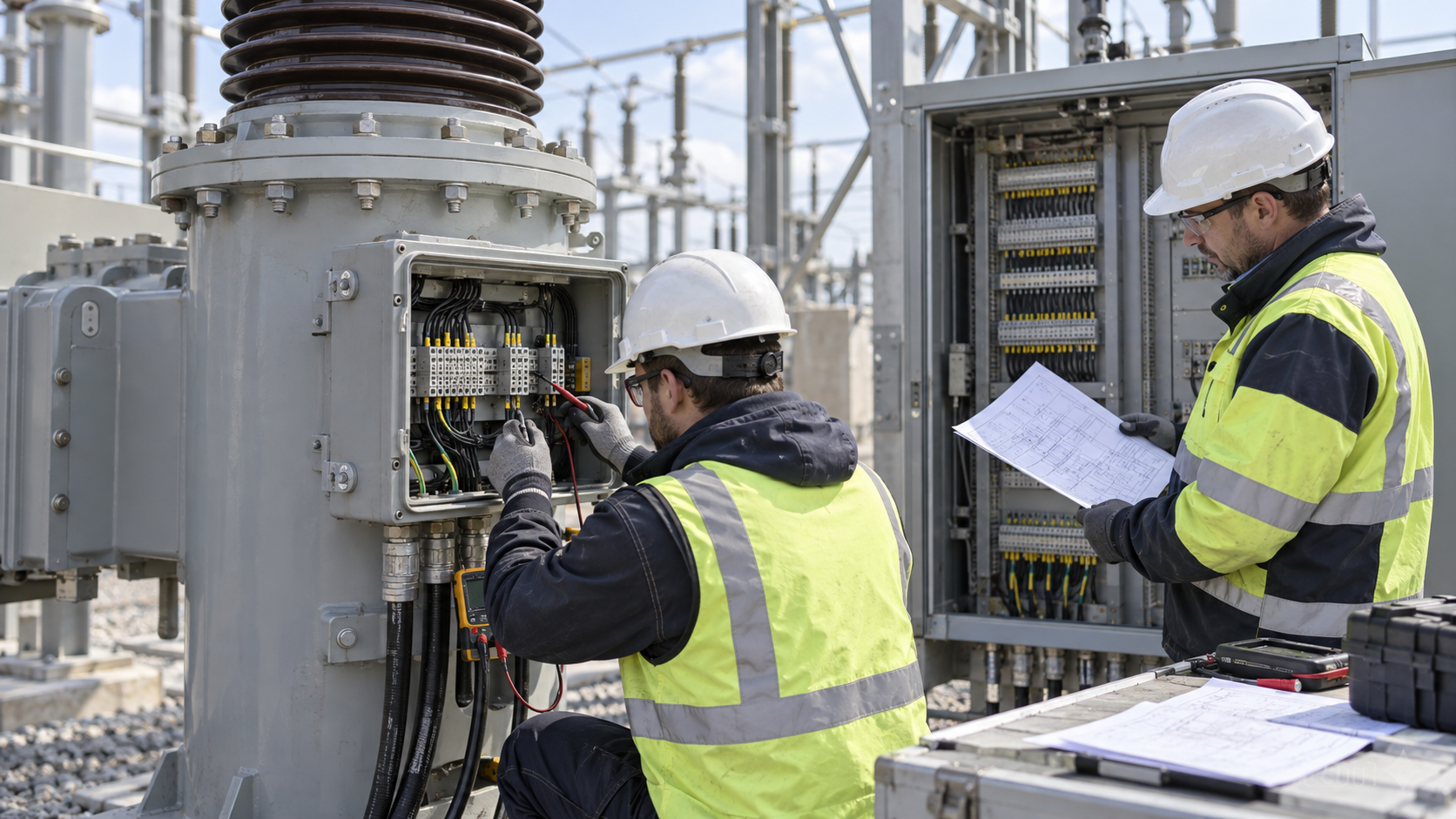
The external insulator is only one part of the bushing interface. The supplier must also coordinate the oil-side end, shield geometry, internal lead connection, flange, gasket, mounting angle and local electric field. These details affect tank-cover design, internal clearances and assembly sequence.
Specify the bushing technology and filling medium only after reviewing service conditions, maintenance capability and owner preferences. If the design uses oil-impregnated paper, resin-impregnated paper or another condenser system, the data sheet should state the construction, sealing arrangement, storage limits and maintenance requirements without relying on ambiguous trade terminology.
Leak prevention depends on clean mating surfaces, compatible gaskets, correct compression and controlled installation. Site teams need approved torque values and assembly instructions. Repeated tightening without understanding the sealing design can damage a flange or gasket rather than correct the root cause.
Where online bushing monitoring is required, define the measured quantities, sensor interface, power supply, communication protocol, alarm philosophy and responsibility for interpretation. A monitor should not be added as an isolated accessory after the transformer and SCADA designs are complete. Its couplers, cabinets and cables must be coordinated with the bushing test taps and grounding arrangement.
Maintenance access should be reviewed from grade level and platform level. Inspectors need safe visibility of the insulator, flange, oil level indication where provided, conductor connection and test tap. Cleaning, electrical testing and bushing replacement require working space and a lifting path. The layout review should include removal envelopes rather than only operating clearances.
The inspection and test plan should link the bushing standard, approved data sheet and project-specific requirements to review or witness points. Verify manufacturer, type designation, serial traceability, rating plate data, capacitance and dissipation-factor records where applicable, routine test certificates, dimensions, terminal hardware, CT data and preservation condition.
During transformer FAT, confirm that installed bushings match the approved drawings and that phase markings, CT polarity, secondary terminals, test taps and monitoring accessories are correct. Dimensional inspection should include terminal elevation, phase spacing and orientation. Any substituted bushing requires a formal technical review because even an electrically acceptable replacement can change clearances, terminal loads or site installation work.
Use a structured transformer FAT witness plan to distinguish document review, inspection, witness and hold points. Photographs and records should identify the actual serial numbers, not generic examples.

On receipt, inspect crates, shock indicators where used, moisture barriers, support blocks and visible porcelain or composite surfaces. Record damage before unpacking is completed. Storage must follow the manufacturer’s orientation, temperature and humidity instructions; a bushing should not be left exposed on unsuitable supports.
Installation checks should cover cleanliness, flange condition, gasket identity, mounting orientation, fastener torque, internal lead connection, terminal hardware, test-tap condition and CT secondary circuits. After assembly, confirm phase identification and required electrical tests. Protection injection and trip-path testing should use the approved CT and terminal references.
The commissioning dossier should contain the approved bushing data sheet, drawings, test certificates, site inspection records, installation checklist, torque record, test results, photographs and closed punch items. Those records establish the baseline for future condition assessment.
A complete enquiry should include the single-line diagram, transformer rating, highest voltage for equipment, insulation levels, rated and fault currents, neutral duty, applicable standards, altitude, pollution data, ambient conditions, conductor arrangement, terminal loads, phase spacing, CT schedule, monitoring requirements, seismic duty, transport limits and required FAT evidence.
Zisheng Electric supports project-specific designs across oil-immersed transformers, substation transformers and transformer manufacturing programs. Interface information should be issued early enough to coordinate the transformer, substation and protection designs before manufacturing release.
To discuss a transformer bushing specification, send your transformer data sheet, insulation-coordination requirements, CT schedule, general arrangement constraints, site-environment data and applicable utility standards. Our engineering team will review the requirements and respond to project inquiries within 24 hours.

Plan substation arc flash study inputs for EPC projects: source fault data, transformer impedance, switchgear geometry, protection settings and as-left handover.
View details
A practical EPC guide to transformer neutral grounding design, NGR sizing, parallel neutral control, protection coordination, factory tests and commissioning evidence.
View details
Plan substation auxiliary power design with station-service transformers, AC/DC loads, batteries, transfer logic and commissioning checks.
View details
Plan high-voltage switchgear commissioning with interface checks, interlock tests, protection verification, control-power proving and energization release evidence.
View details