 zishengelectric



news
News Center
Providing high-quality power to the world
Search productSearch post
news
Providing high-quality power to the world
Zisheng Electric treats substation fiber optic acceptance as an EPC handover decision that connects installed cables to working protection, control and monitoring functions. A neat communications cabinet does not demonstrate a usable network. One patch lead at the wrong port can leave a relay visible at the local panel but missing from the operator workstation, or can turn a specified redundant path into two links sharing the same failure point.
This article focuses on the acceptance boundary between cable contractor, panel supplier, network integrator and owner. It does not prescribe one optical loss limit or a universal protocol setting. The approved design, equipment transceiver data and project test procedure determine those values. The goal is a traceable path from the as-built fiber to the application signal and an evidence package the operating team can use after the EPC contractor leaves.
First list the functions that depend on each fiber path. These may include relay-to-relay protection messaging, bay controller traffic, engineering access, station gateway communication, operator displays, condition monitoring and remote control. Some paths are service-critical while others carry maintenance data. An optical link can pass a cable test and still fail to support the intended application because ports, network settings or point mappings are wrong.
Agree where the acceptance responsibility starts and ends. Is the fiber contractor responsible through the patch panel, through the patch lead, or to the device port? Who owns the active network switches, transceivers, power supplies and configuration files? Identify the party responsible for the end-to-end application test as well as the person authorized to accept it. Link this register to the transformer protection interface matrix so that critical trips and alarms have a named verification route.
Use an interface record with unique identifiers for source cabinet, patch panel, fiber core, destination cabinet, device port, network function and test sheet. The identifier should appear on drawings, labels and results. If a vendor changes the port assignment, update the record before testing. Accepting a connection under an old identifier creates a handover problem even when the signal works at the time.
Physical route inspection confirms what was installed. Optical measurements confirm that the cable and connectors perform within the approved link budget. Network checks confirm that devices communicate as designed. Application testing confirms that the intended status, alarm, event or control action reaches the correct recipient. The evidence is cumulative; a green switch-port indicator is not a substitute for a point-to-point test or a protection functional test.
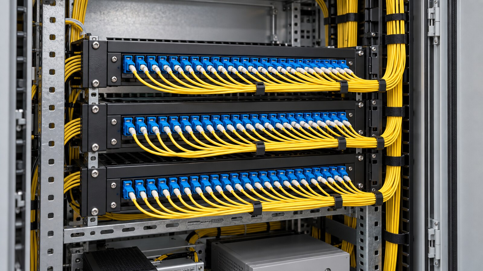
A network diagram should show cabinets, switches, patch panels, communication paths and power sources. Mark every physical route and every logical or operational redundancy requirement. If two supposedly independent links share the same tray, cabinet entry or auxiliary supply, the owner needs to know which failure they are actually protected against. Record the approved design case rather than assuming that duplicate cables are independent.
The substation auxiliary power system guide is useful because a network switch or gateway may lose communication when its DC supply fails. Include the active equipment power feed in the interface register. During acceptance, test the behavior of the specified alternate path and record what happens when a single source, link or network element is intentionally isolated under an approved safe procedure.
The EPC team also needs a cable schedule with end points, route lengths, connector type, fiber type, core allocation and spare cores. Put the fiber in the same document-control process as power and control cables. A schedule is useful only if it matches installed tags and cabinet drawings. Where a subcontractor supplies preterminated assemblies, confirm that delivered connector and polarity details match the approved devices and patch panels.
Before testing, define the link budget from the selected transmitters, receivers, cable and passive components. The acceptance threshold must be approved for that particular path. Do not copy a loss value from another project without checking fiber length, connectors, splices, wavelength and equipment margins. The contractor should document the test instruments, calibration status, test method, launch and receive arrangements when applicable, direction and wavelength.
For a failed measurement, preserve the original result, record the repair and retest the affected path. Replacing a connector without a deviation record can break traceability. The final test set should identify every core, including unused or spare cores if the contract calls for them. If some cores cannot be tested because the equipment is not yet installed, list the open items and assign a closing milestone rather than marking the cable system complete.
Check that the installed cable is the specified construction and that the route protects it from crushing, sharp edges and unintended pulling tension. Verify tray covers, cabinet entry protection, splice enclosures and accessible service loops against the approved installation detail. A link can pass a measurement today while poor mechanical protection creates a later fault. Record the condition when the route is still visible; concealed work is harder to prove after civil finishes are complete.
Inspect connector handling and cleanliness according to the component manufacturer’s instructions before mating. Keep optical end faces protected while cabinets are open for other trades. If a link fails, compare the physical route and recent handling history before replacing active electronics. This sequence reduces unnecessary device changes and keeps the actual defect visible in the project record.
| Acceptance gate | Evidence to retain | Engineering decision enabled |
|---|---|---|
| Route and cabinet inspection | As-built routing, bend protection, separation and cabinet-entry photographs where appropriate | Confirms the physical route and maintainable access. |
| Fiber identification | Core and port schedule matched to labels at both ends | Prevents cross-connection during testing and future repair. |
| Optical performance | Approved budget, instrument record and core-by-core results | Shows whether the installed link supports the selected equipment. |
| Network resilience | Topology and controlled single-failure test record | Checks the intended alternate path rather than presumed redundancy. |
| Application signals | Point-to-point and functional test sheets | Confirms correct meaning, destination and operator response. |
| Handover | Configuration backup, as-built drawings, open-item list and support ownership | Allows safe operation and later fault tracing. |
Some EPC specifications invoke the IEC 61850 family for utility automation. The IEC states that IEC 61850-3 covers general construction, design and environmental requirements for utility communication and automation equipment, while IEC 61850-10 with its 2025 amendment concerns conformance-testing techniques. Neither citation by itself proves that the project’s complete installed network and application logic have passed site acceptance. The contract should name the relevant editions, devices, services and project-specific tests.
Ask the system integrator to provide the network architecture and approved settings, including addressing, time synchronization, switch configuration, protocol roles and configuration files where required. Protect the accepted version through change control. A protection relay may have passed its own factory test but still have the wrong message subscription, timing arrangement or gateway mapping at site. The acceptance file should connect the software version and network configuration to the test results.
If the utility or owner specifies a particular communication interface, request its written requirements and agreement to the test procedure. Do not infer the accepted network design from a country or a generic standard name. Regulatory and utility conditions vary by project and cannot be filled in from an unrelated plant.

A redundant drawing deserves a deliberate test. Define the normal configuration, the single failure to simulate, expected traffic behavior, permitted interruption, alarm and restoration step. Isolate only under a written procedure approved by the commissioning lead. Record observed results and any deviation. A cable break, switch power loss and transceiver failure are different events; the test matrix should reflect the failures relevant to the accepted design.
Physical diversity needs its own check. Two links leaving the same cabinet through one unprotected opening may be vulnerable to one construction incident. If true separation was not part of the contract, say so in the handover record. If it was required, demonstrate it with as-built route evidence. This matters to owners who will rely on the communications system for operational decisions after project closeout.
Test a representative set of indications and controls from the originating device to the intended display and back where a command is specified. Include alarm text, state sense, timestamp, engineering units and loss-of-communication behavior. For protection functions, use the approved protection test plan and experienced commissioning personnel; do not operate a live trip path casually to prove a communications point.
An event may reach SCADA while its meaning is reversed or its timestamp is wrong. A display may show a healthy communication symbol while a configured alarm is suppressed. Record expected result and observed result for each point, then close exceptions with a responsible owner and retest evidence. Tie the outcome to the transformer GIS interface guide when a cable or communications route passes between a transformer, switchgear and protection cabinets.
When the station gateway communicates to a remote control center, include the external interface authority in the witness plan. The local EPC team can verify its own ports and configuration, but remote acceptance needs the actual receiving organization and approved access window. Distinguish “ready for remote test” from “accepted by remote operator” in the punch list.

Deliver as-built routes, splice and patch schedules, optical test results, device port mappings, network configuration backups, application test sheets, software versions, approved deviations and outstanding issues. Identify spare fibers and spare optical modules, with storage and compatibility information. Give the owner a fault-isolation guide showing the first checks when one device disappears from the network; a stack of unindexed PDFs is much less useful during an outage.
Training should cover safe access to cabinets, change approval, backup and restore responsibilities, and the boundary between owner and vendor support. If a later modification reassigns ports or patches, update the same register used for acceptance. This preserves the meaning of the test evidence rather than letting the as-built record become obsolete after the first maintenance task.
Zisheng Electric’s prefabricated substation and medium-voltage switchgear can be considered as part of a wider EPC equipment package. The exact communications scope, relays and interfaces must be agreed for the offered project configuration; these product pages do not claim a pretested fiber network.
For substation fiber optic acceptance, send Zisheng Electric the drawings, device and equipment data sheets, load list, technical specification, single-line diagram, grid parameters, environmental conditions and installation-site conditions. Include the fiber route and core schedule, network topology, optical link budget, SCADA point list, protection philosophy, test procedure and the owner’s handover criteria. We can help identify missing supplier boundaries and the evidence required before a connection is signed off. Our engineering team will review the requirements and respond to project inquiries within 24 hours.

Review substation bolted connection records: verify torque instructions, tool traceability, witness marks and reassembly evidence before EPC handover.
View details
Plan substation relay settings handover: check approved files, relay identity, active groups, readback comparisons and changes before EPC closeout.
View details
Plan substation HMI mimic acceptance with equipment labels, status interpretation, measurement meaning, data-quality checks and controlled handover records.
View details
Build a substation temporary modification register that connects approved test changes to baseline records, restoration checks and release evidence. Review ownership, shift handover, configuration reconciliation and operator turnover.
View details