 zishengelectric



news
News Center
Providing high-quality power to the world
Search productSearch post
news
Providing high-quality power to the world
Zisheng Electric sees the substation lightning mast interface as a coordination task across electrical, civil and construction disciplines. A mast on a site layout is only a location. It does not explain the lightning-risk basis, protected volumes, foundation reactions, earth connection, underground services, construction sequence or ownership of final inspection. EPC teams should close these decisions before concrete, cable trenches and transformer bays are fixed.
This guide concerns a hypothetical substation project, not an actual customer installation or completed lightning design. The appointed lightning-protection designer must determine whether a mast is needed, where it belongs and how its protection performance is verified. The transformer supplier can provide equipment geometry and connection data; it cannot approve a site-wide protection concept without the site studies.
Start with the project risk assessment and the scope of the protected facility. IEC 62305-2:2024 addresses lightning risk management for structures. IEC 62305-3:2024 covers physical damage protection using a lightning protection system and nearby touch and step voltage hazards. Whether and how these documents apply to the particular substation must be set in the project design basis along with utility rules and local requirements. Neither reference supplies a universal mast height or location for every transformer yard.
The designer should identify assets that need protection, such as power transformers, outdoor switchgear, control buildings, cable terminations, communication equipment and personnel routes. Distinguish direct-strike interception from surge protection at equipment terminals. A tall mast may change the physical strike exposure; it does not replace insulation coordination, surge arresters, grounding design or the protection of control circuits.
Overlay the proposed mast location and protection assessment with the latest transformer outline, bushing elevations, busbar geometry, GIS or switchgear position, cable routes, maintenance crane envelope and future expansion bays. A two-dimensional circle drawn on a plot plan cannot prove three-dimensional coverage or the safety of clearances. Review any shadowed area, high accessory or future structure with the method the designer has adopted.
Air terminations, structural steel and live conductors need the separation required by the approved electrical and lightning design. The drawings should show their actual elevations and installation tolerances. If the mast is near a transformer, check the crane path for bushing replacement and radiator removal. The mast must not make routine oil sampling, firefighting access or an emergency vehicle turn impractical.
Compare the equipment arrangement with Zisheng Electric’s transformer and GIS interface guide. That article deals with terminals and equipment boundaries; the mast design must use the final dimensions that result from those interfaces.
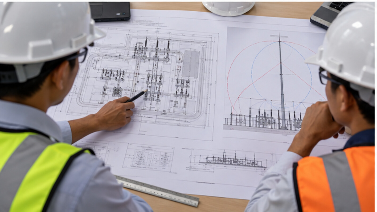
| Interface | Responsible input | Drawing or calculation | Release check |
|---|---|---|---|
| Risk and protection basis | Owner and lightning-protection designer | Adopted method, facility scope and assessment revision | Mast need and protection concept approved |
| Equipment envelope | Transformer and switchgear suppliers | Final GA, elevations and maintenance clearances | Protected-volume study uses matching revision |
| Foundation and anchors | Civil designer with mast supplier | Reaction, soil, concrete and anchor details | Foundation release before excavation |
| Earth connection | Earthing designer and installation contractor | Bond route, grid connection and test location | As-built continuity and inspection record |
| Underground conflict | Civil and cable contractors | Utility survey and combined buried-services plan | Excavation permit and hold point |
| Access and future bays | EPC layout lead and operator | Crane, vehicle and expansion study | Site walkdown and signed interface closure |
The table is a decision aid, not an assignment of statutory duty. The contract must state who signs the risk study, who designs the mast and who accepts the completed installation. “By others” on a supplier drawing is not a closed engineering interface.
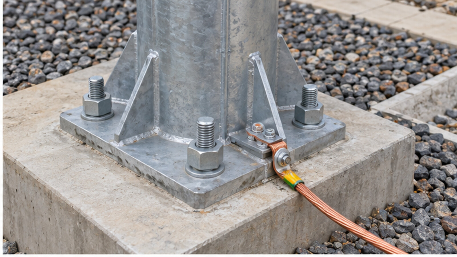
A mast foundation needs the supplier’s design reactions and geometry, the civil designer’s geotechnical parameters and the project’s wind and other governing actions. The anchor cage, conduit entry and reinforcement have to fit the actual base and erection method. Do not copy a footing size from another site or assume that a structural slab can take the mast load without a calculation.
Identify underground services before setting coordinates. Grid conductors, fiber ducts, drainage, oil-containment pipework and fire-water lines may all occupy the proposed footprint. The cable and civil teams should sign a combined services drawing, including the construction tolerance and the clearance needed for excavation equipment. A mast moved late to miss a cable trench may no longer satisfy the approved protection study.
For a substation refurbishment, confirm foundation condition and survey the as-built yard. Red-line drawings may omit buried changes. Use a controlled field-verification method before excavation, then send the actual coordinates back to the designer. If obstructions force a relocation, revise both the civil detail and the protection assessment before concrete is poured.
The lightning down-conductor and earth termination arrangement belongs to the approved lightning and substation earthing design. Locate the bond point, conductor route, mechanical protection, inspection joint if specified and any test access on the drawing. The route should remain inspectable after gravel, paving and fencing are installed. Avoid a sharp, inconvenient detour just to follow the nearest civil edge without reviewing the surge-current path.
High transient currents can create hazardous potential differences. The earthing designer must evaluate the station grid, adjacent metalwork, step and touch exposure, cable screens and control wiring under the adopted method. The transformer earthing interface guide explains the equipment-side bonds and controlled core links; the mast connection is another site-wide interface, not an excuse to bond a transformer core test link arbitrarily.
Show where the lightning protection system meets nearby fencing, rails and structural steel. The team should use the approved bonding philosophy and verify continuity where the design requires it. The transformer neutral earthing path remains a separate system function even if it eventually connects to the same grid.
Transformers and switchgear may need surge arresters or other measures selected through insulation coordination. The mast does not determine their rated voltage or placement by itself. Obtain the system highest voltage, earthing arrangement, temporary overvoltage duty and equipment insulation levels from the electrical study. Then show arrester positions, line leads, earth leads and maintenance access on the coordinated GA.
Long or poorly routed connections can affect the protective voltage seen at the equipment. The physical layout therefore matters even when a device’s catalogue rating is correct. Confirm whether arresters are supplier-mounted or EPC-installed and which party provides brackets, conductors, counters and test points. The purchasing package should make these supply boundaries visible to all bidders.
If the substation includes a prefabricated building or compact yard, consider how roof conductors, cable entrances and control interfaces relate to the external mast concept. Zisheng Electric’s prefabricated substation product may be relevant to the equipment package, but its protection arrangement still requires a project-specific engineering review.
A long mast may arrive in sections and require a crane, temporary support or a defined laydown area. Check delivery route, lifting radius, proximity to live circuits, permit boundaries and working sequence. The mast should not be erected over energized equipment without an approved method and isolation plan. If a future transformer replacement crane will pass nearby, reserve that envelope now and define whether the mast can remain in place.
Specify corrosion protection using site conditions: humidity, salt exposure, pollution, solar radiation and the maintenance plan. A coastal site and an inland dry site should not receive the same specification merely because both have a transformer yard. Detail the base drainage, coating repair, hardware accessibility and inspection frequency required by the owner. The design should identify how a technician can safely inspect the bond and mast base after the station is operating.
Transport and installation conditions may change the interface. A slightly different steel section or base plate delivered by a subcontractor can alter the anchor arrangement. The EPC document register must track the accepted mast supplier data, construction drawing and as-built dimensions against the approved protection study.
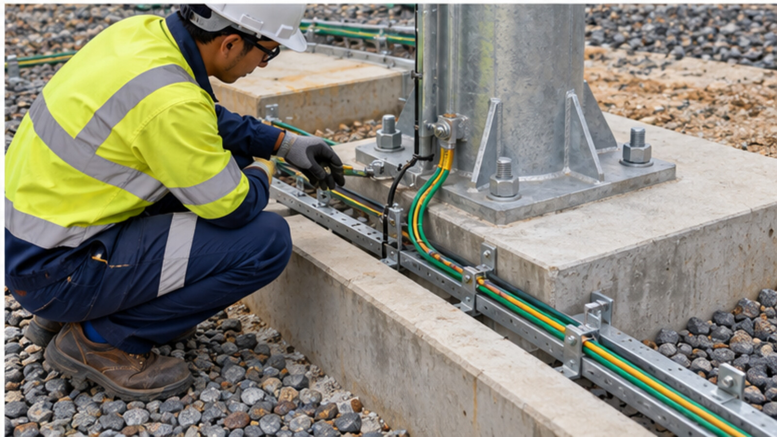
Factory documentation can establish the mast material, section dimensions, protective finish, anchor hardware and identified components. It cannot demonstrate the completed grid connection or the actual protection coverage of a differently located mast. At site, inspect foundation position, anchor installation, verticality, section joints, corrosion protection, earth continuity and the installed equipment envelope. Record test methods and acceptance criteria from the approved project documents.
The commissioning file should include the risk study, coordinated GA, mast and foundation drawings, equipment elevations, anchor and concrete records, earthing as-builts, continuity results, deviation log and signed close-out. The transformer commissioning punch list provides a related method for assigning owners and evidence to unresolved site items. A photograph of a completed mast cannot replace this technical record.
Protection geometry can change when a transformer bushing height, switchgear bay, building roof or future expansion plan changes. Add the lightning study to the documents affected by these revisions. The EPC coordinator should issue a formal change notice to the protection designer, civil engineer and earthing designer when an equipment envelope changes, then capture their responses before the revised arrangement is accepted. A new drawing number in one discipline is not evidence that all other design assumptions were rechecked.
When two suppliers use different coordinate systems, establish one common site datum and elevation reference. Identify the origin on the general arrangement and the foundation setting-out drawing. Record survey tolerances and an as-built check after erection. This simple discipline prevents a mast from being placed on a visually convenient grid line that does not match the approved protective geometry. Keep earlier study revisions available so reviewers can understand which equipment change triggered a relocation.
Procurement should distinguish included scope from optional scope: mast, foundation hardware, down conductors, test joints, surge devices, earth conductors, coating repair and site testing may be supplied by different contractors. A clearly priced boundary lets the owner compare bids and schedule handovers without creating an unassigned gap.
For a substation lightning mast interface review, send Zisheng Electric the site drawings, transformer data sheets, load list, technical specification, single-line diagram, grid parameters, environmental conditions and installation constraints. Include the lightning-risk basis, earthing study, proposed mast positions, foundation information, cable and drainage plans, future bay layout and utility comments. We can coordinate the equipment dimensions and interfaces for power transformers and medium-voltage switchgear while the appointed designers close the site-wide protection design. Our engineering team will review the requirements and respond to project inquiries within 24 hours.
Plan high-voltage switchgear commissioning with interface checks, interlock tests, protection verification, control-power proving and energization release evidence.
View details
Plan substation auxiliary power design with station-service transformers, AC/DC loads, batteries, transfer logic and commissioning checks.
View details
Define transformer OLTC control interfaces for AVR measurement, raise-lower commands, tap position, parallel operation, FAT and commissioning.
View details
A practical EPC guide to transformer neutral grounding design, NGR sizing, parallel neutral control, protection coordination, factory tests and commissioning evidence.
View details