 zishengelectric



news
News Center
Providing high-quality power to the world
Search productSearch post
news
Providing high-quality power to the world
A substation sump pump specification should explain what happens when water arrives and equipment is unavailable. Zisheng Electric treats this as an interface between civil drainage, station auxiliary power, controls and maintenance access. Specifying two pumps and a control panel is only the beginning. The EPC team must show that the arrangement can remove the expected inflow, announce a developing failure and remain maintainable without exposing electrical equipment to avoidable flooding.
This engineering briefing addresses a clean-water drainage sump serving a substation building or approved drainage area. It does not cover automatic discharge of oil-contaminated water from transformer containment. Those systems need a separate environmental and fire-design review, including the approved discharge route and operating controls.
Start with a drawing showing where water comes from, where it collects and where it can safely leave. The civil designer should establish the contributing area, design inflow and relevant groundwater assumptions. The discharge destination needs an identified owner. If the downstream drain can surcharge, the pump duty must be reviewed against that condition rather than an optimistic normal water level.
Record the consequence of failure. Water in a remote external chamber and water approaching a cable basement do not have the same operational significance. Identify the lowest vulnerable opening, equipment support level and any overflow path. These elevations turn an abstract high-level alarm into a meaningful intervention deadline.
Keep the hydraulic calculation, electrical load schedule and control sequence linked to the same revision. A late increase in discharge-pipe length can change the operating point. A changed motor can affect starting current and protective settings. A raised floor can alter available storage. None of these changes should remain inside one contractor’s drawing package.
| Decision | Required design input | Evidence to request |
|---|---|---|
| Duty capacity | Approved inflow cases and total dynamic head | Pump curve with the proposed duty point and operating limits |
| Standby philosophy | Capacity required with one pump unavailable | Explicit single-pump and combined-pump performance cases |
| Usable storage | Chamber geometry, operating levels and vulnerable elevations | Level schedule and time-to-critical-level calculation |
| Power availability | Normal supply, outage duration and recovery sequence | Auxiliary-power study and tested restart logic |
| Failure detection | Pump, level sensor and discharge-path failure cases | Cause-and-effect schedule with alarm destinations |
| Maintenance access | Removal route, isolation, lifting and safe working area | Coordinated layout and equipment-removal method |
The pump supplier needs the required flow and the head against which it must operate. Include static lift and losses through pipes, fittings, valves and the discharge arrangement. Ask for the expected operating range as water levels change. A larger motor rating alone does not prove that the proposed pump meets the duty.
The Grundfos explanation of non-return valves notes their one-way-flow function and associated head loss. That is a useful reminder to include the selected valves in the hydraulic calculation. Check accessibility and maintenance provisions as well as their effect on the duty point.
The term “duty/standby” should mean something testable. If one pump is expected to handle the design duty, demonstrate that case with the other pump unavailable. If both pumps are needed to remove the peak inflow, the installation has a different resilience profile. Describe that arrangement honestly and establish what happens when a pump is out of service during heavy inflow.
Two identical pumps do not necessarily deliver twice the single-pump flow through a shared discharge line. The system resistance changes with flow. Request the combined operating point and check it against the piping arrangement. This matters when a controls contractor proposes starting the second pump at a higher level without confirming the resulting hydraulic performance.
Alternating the lead pump can distribute operating hours, but it is not proof that both pumps remain healthy. Provide a way to observe run status, fault status and accumulated duty. Define how the controller handles a failed start, a trip during operation and a unit deliberately isolated for maintenance.
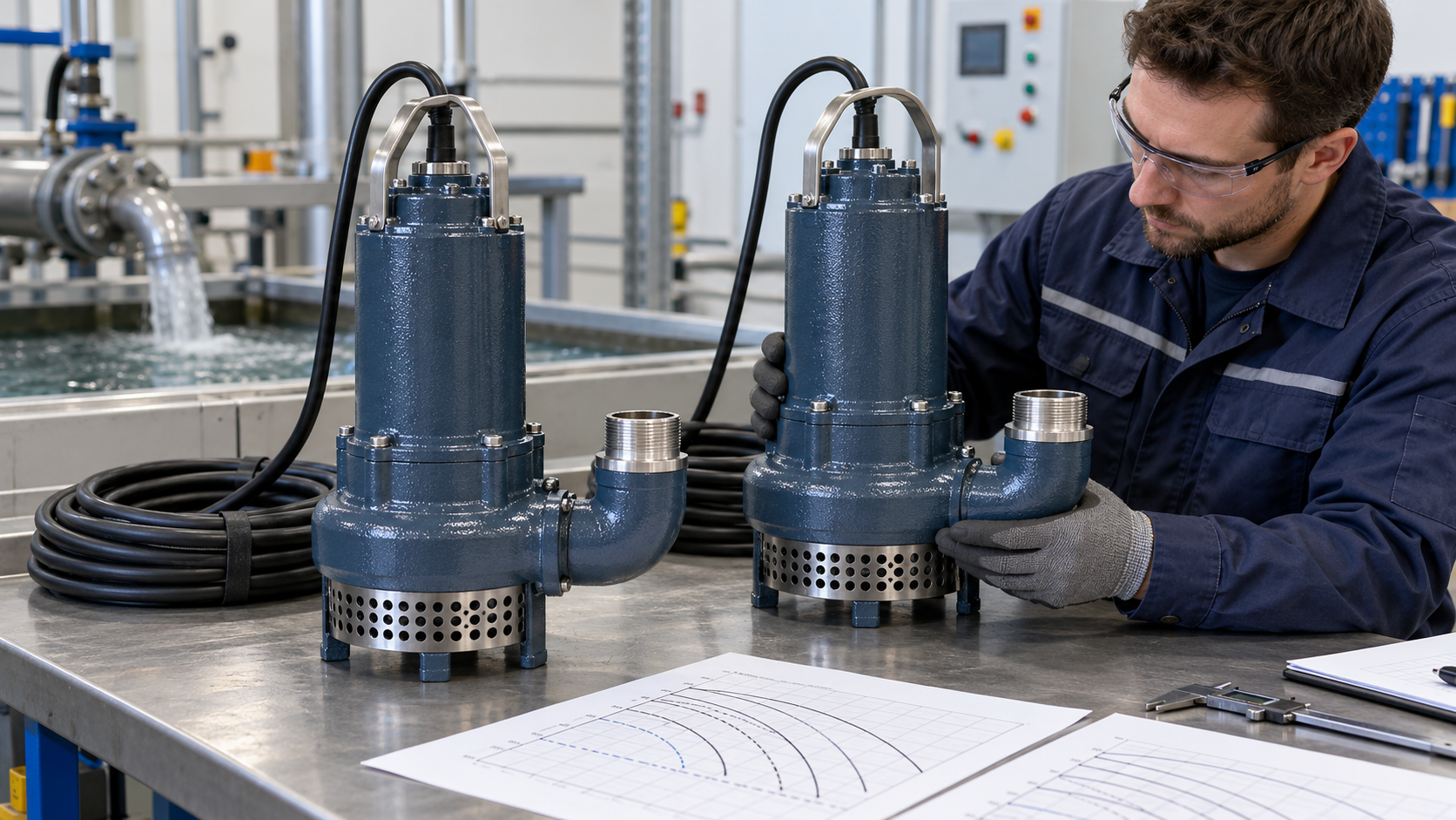
Specify the signal that identifies failure and the permitted response. A motor contactor indication may confirm a command or contact position; it does not, on its own, demonstrate that water is leaving the sump. Decide whether the design needs current, flow, pressure or level-trend evidence, taking account of the equipment and the consequence of a missed failure.
The standby-start sequence should have defined conditions and a clear alarm. Maintenance personnel need to know which unit failed, whether the other pump is running and whether the level continues to rise. Avoid a single undifferentiated “pump fault” signal if it prevents a useful remote assessment.
Review stuck, fouled, disconnected and implausible level signals. Establish the normal stop level, lead-start level, any additional pump-start level and the high-level warning. Their exact arrangement depends on the selected sensing method and the approved control philosophy; it is not a universal requirement for a particular number of float switches.
The Xylem packaged pump-station handbook provides an example of dual-pump control using stop, duty-start, standby-start and high-level functions, with alternation. Use such manufacturer guidance to inform the review, then document the actual project’s setpoints, sensor arrangement and failure responses.
Consider whether the warning function needs independence from the normal control sensor. If the same failed sensor defeats both pumping and warning, a second pump alone does not resolve the common failure. The designer should explain how the proposed arrangement addresses this risk.
A running pump can coexist with a closed isolation valve, a blocked line or an unavailable receiving drain. Identify how these conditions will be detected and who is allowed to change valve positions. Mark normal operating positions and preserve access to the parts that need inspection.
Review backflow after a pump stops and the effect of a downstream high-water condition. Do not assume that an external drain remains available during the same storm that produces the largest inflow. The civil and mechanical designers should agree the governing discharge scenario and the resulting limit on performance.
List the pumps and controls in the station service load schedule, including starting conditions and any backup-source proposal. Connect this review to the wider substation auxiliary-power design. A spare pump on the same unavailable supply does not provide power-source redundancy.
Where the design relies on storage during an outage, calculate how much time is available before water reaches a critical elevation. Where it relies on a standby supply, verify the transfer sequence, starting capability and simultaneous loads. Do not assume an instrument UPS can supply pump motors simply because it keeps the control panel alive.
An alarm setpoint needs a response-time basis. Calculate usable volume between the warning level and the critical level, accounting for the actual chamber shape. Divide that volume by the net inflow for the stated failure case. If pumping is unavailable, net inflow is the inflow itself; if a remaining pump still operates, use its demonstrated removal rate under that condition.
For a simplified illustrative check, 3 cubic metres of usable storage and a constant net inflow of 0.5 cubic metres per minute provide six minutes before the critical level. These are invented design-example values, not recommended settings. Such a short interval would demand a very different response from a sump with hours of reserve. Use a time-varying calculation when the inflow or chamber geometry makes the simple estimate inadequate.
Compare the resulting time with detection, communication, operator acknowledgement, travel and intervention. If the response cannot be completed in time, change the engineering provision. Raising an alarm priority does not create additional drainage capacity or shorten an inaccessible maintenance route.
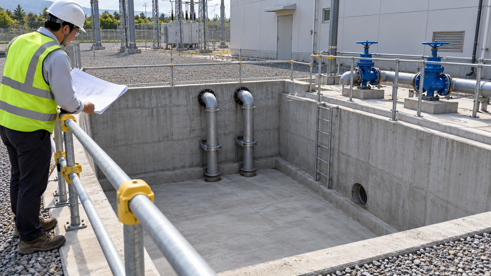
The drainage drawing should identify every inlet and destination. Do not connect a clean-water sump automatically to a transformer bund merely because the pipe route is convenient. An oil release can change the suitability of the pump, the discharge controls and the environmental consequences of automatic operation.
Use a separate transformer oil-containment design review for bund water, spill management and any treatment or discharge arrangements. Establish the applicable local requirements through the responsible project specialists. This article does not prescribe a discharge consent, separation efficiency or containment volume.
Physical separation also helps maintenance staff understand which system they are operating. Label the drainage service and valves consistently with the drawings, and include the destination in the handover information. Where cross-connections exist by design, their purpose and controls need explicit approval.
Review pump removal before the chamber and building layout are frozen. Establish the lifting route, connection method, cable handling, isolation points and working space. A pump that meets its hydraulic duty but cannot be removed safely is an incomplete design. Access should not require entering an energized electrical enclosure or obstructing essential switchgear operation.
Coordinate the drainage package with the surrounding electrical equipment. For a prefabricated substation package, agree enclosure openings, floor levels and cable-entry interfaces. For the adjacent medium-voltage switchgear installation, verify that drainage access and discharge routes do not conflict with equipment access or replacement space.
Include spare sensor availability, pump replacement identification and the information needed to order compatible parts. Record cable lengths and termination details when they affect replacement. A maintenance manual should describe the installed arrangement rather than a generic product family with several possible control schemes.
Agree an approved test procedure with the relevant contractors. Confirm safe isolation and controlled test-water arrangements before testing. Demonstrate normal start and stop, alternation where provided, the response to one unavailable pump, high-level alarm transmission and the agreed recovery sequence after loss of power. Do not create an uncontrolled flood condition to prove an alarm.
Record measured levels, pump identity, control settings, alarm receipt and any observed restrictions. Verify that indications at the local panel and remote operator interface describe the same equipment state. Close defects against a repeated test of the affected function; a corrected drawing alone does not prove the installed logic works.

The handover package should contain the final hydraulic basis, pump curves, coordinated layout, power and control diagrams, level schedule, cause-and-effect record, test results and maintenance instructions. Identify any operating restriction that remains. Assign ownership of periodic functional checks so the standby arrangement does not become an untested assumption after energization.
Zisheng Electric can review transformer and substation electrical-package interfaces alongside the EPC team’s drainage design. For a substation sump pump specification review, provide the single-line diagram, auxiliary load list, drainage drawings, pump data sheets, control sequence, environmental conditions and site installation constraints. The responsible civil and pump designers should supply the hydraulic and discharge basis. Our engineering team will review the requirements and respond to project inquiries within 24 hours.

Coordinate transformer fire protection for EPC projects: separation, oil containment, drainage, detection, suppression, control logic, FAT and site testing.
View details
Coordinate transformer condition monitoring for EPC projects: sensors, SCADA points, alarm ownership, communications, FAT, commissioning and data handover.
View details
Coordinate substation underground services before excavation: resolve cable, drainage and earth grid clashes, assign decisions and capture buried-work records.
View details
Coordinate transformer earthing interfaces for EPC projects: tank bonds, neutral grounding, core links, cable screens, surge arresters, FAT and handover.
View details