 zishengelectric



news
News Center
Providing high-quality power to the world
Search productSearch post
news
Providing high-quality power to the world
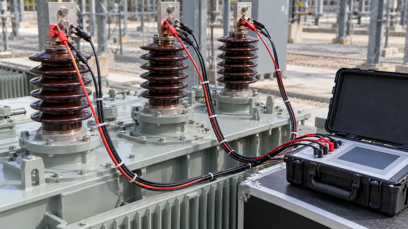
For an EPC transformer package, an induced voltage withstand test is not a box to tick after the test schedule is issued. The winding, insulation level, test connection, voltage waveform, frequency, duration, and acceptance basis must all match the approved design and applicable standard. Zisheng Electric’s project teams can help align the FAT document set before the witness point so the owner, EPC contractor, and manufacturer are reviewing the same test boundary.
An induced voltage test applies a controlled alternating voltage through a transformer winding to create the specified dielectric stress in the insulation system. The source frequency and connection are selected for the transformer design and the test procedure. The purpose is to demonstrate withstand capability under the applicable test conditions, not to reproduce every feature of normal operation or to generate a generic pass/fail value that can be carried from one transformer rating to another.
Terminology varies between specifications and test plans. An induced voltage withstand test may be described as IVW or as an induced AC withstand test. An induced voltage test with partial-discharge measurement is a distinct specified test arrangement, commonly called IVPD. When PD measurement is required, it has its own measurement circuit, calibration, background-noise assessment, and contractual acceptance criteria. A plain IVW report should not be presented as a PD test, and the absence of PD readings in an IVW record is not, by itself, a missing result.
Before FAT, confirm the winding being energized, the terminals and connections, which other windings are grounded or connected as required, the test voltage and its reference, the applied frequency, duration, and any specified measurements. These are project-specific variables. The correct levels depend on winding ratings, insulation coordination, terminal configuration, the applicable test category, and the contract’s adopted standard and edition. Avoid inserting a “typical” voltage table unless it is traceable to the exact project data and standard clauses.
The FAT procedure should reconcile the transformer nameplate and approved drawings with the insulation-level schedule and test sequence. It should state the test source capability, connection diagram, voltage measurement point, ramp-up and ramp-down method, protection and trip arrangements, and the records to be retained. If the project requires PD measurement during an induced test, the procedure should identify that requirement explicitly rather than implying it from the phrase “induced voltage test.”
| FAT review item | Evidence to check | Decision purpose |
|---|---|---|
| Design basis | Winding voltage ratings, terminal arrangement, insulation schedule, and approved drawing revision | Confirms the test applies to the equipment actually being built. |
| Test category | Specified induced withstand test or induced test with PD measurement, named in the ITP | Prevents different test scopes from being treated as interchangeable. |
| Test circuit | Energized winding, neutral and phase connections, grounding of other windings, and measuring point | Allows another reviewer to reconstruct the setup. |
| Source and waveform | Frequency, voltage measurement method, stability, and source capacity | Shows the test conditions were controlled and suitable for the transformer. |
| Acceptance and disposition | Applicable standard, contract criteria, interruption rules, and sign-off authority | Provides a traceable basis for the release decision. |
Transformer flux is related to applied voltage and frequency. When the test voltage is higher than rated voltage, a suitably selected test frequency is used so the core is not driven into excessive flux during the procedure. The actual frequency and test duration must follow the applicable standard and approved method for the transformer under test; they should not be copied from an unrelated FAT. A test log should record the measured frequency and voltage, the actual duration at the specified level, any interruptions, and the reason for each deviation.
The project team should also confirm whether the source and measurement system can maintain the required conditions for the duration of the test. Instrument range, voltage divider or measuring transformer details, calibration evidence, protective trips, and a clear stop criterion are part of the test record. If the test is interrupted, the procedure must determine whether a repeat or alternative disposition is required; the witness team should not invent a restart rule on the test floor.
For the same winding, core geometry and approximately sinusoidal waveform, peak flux density is proportional to V/f. In an illustrative calculation, applying 2.0 times a winding’s reference voltage at 2.0 times its reference frequency gives a relative V/f of 2.0/2.0 = 1.0. This explains why increased frequency can limit core excitation during an induced test. It does not prescribe a two-times-voltage test, establish a permitted frequency, or prove that the resulting dielectric stresses satisfy a particular transformer specification.
The approved procedure must still establish the actual voltage, frequency and duration from the applicable clauses and equipment design. It must also identify whether reported voltage is phase-to-phase or phase-to-neutral and where it is measured. A correct V/f calculation cannot compensate for the wrong test connection or voltage reference.
| Record presented | EPC acceptance question |
|---|---|
| IVW completed, but the contract requires induced testing with PD measurement | Where is the specified PD circuit, calibration, measurement and acceptance evidence? |
| Specified level was reached, but the test was interrupted | Does the documented disposition follow the approved interruption and repetition rules? |
| Report states a voltage with no terminal reference | Can the recorded stress be reconciled with the approved connection diagram and insulation schedule? |
A witness plan is strongest when it separates hold points from review points. The witness should verify equipment identity, the approved procedure revision, the connections before energization, the measuring arrangement, and the actual recorded test conditions. The signed report should retain the test circuit, equipment serial number, relevant winding and terminal identification, voltage and frequency records, timing, interruptions or alarms, and the final disposition. Include instrument calibration references and the name of the responsible test authority.
Review the trace or log against the agreed criteria, not against an informal expectation from a previous project. A stable voltage record and a completed duration support the evidence chain; they do not authorize a reviewer to infer a result beyond the stated test scope. If the test team observes abnormal current, audible discharge, protection operation, or another unexpected event, record the observation and follow the approved investigation process. Do not convert a single observation into a diagnosis without technical review.
For a commissioning or procurement engineer, this distinction matters at handover. If the owner’s specification asks for IVPD, an IVW-only record cannot silently substitute. Conversely, if the specified requirement is IVW, adding an unapproved PD threshold after testing can create a false nonconformance. The ITP and contract should resolve the intended scope before manufacture reaches the FAT stage.
IEC 60076-3:2013+AMD1:2018 covers insulation levels, dielectric tests, and external clearances in air for power transformers. The project should identify the applicable edition and test requirements, then apply any purchaser-specific additions through the contract and approved ITP. IEEE requirements may apply on projects designed to IEEE standards; do not mix criteria from IEC and IEEE documents without an explicit engineering basis.
For related testing, see the site’s transformer partial-discharge FAT review, which addresses the PD measurement scope, and the tap-by-tap turns-ratio verification guide. A project transformer such as the 35 kV / 46 kV power transformer range must be evaluated using the selected unit’s approved insulation schedule and project specification.
These checks make the test package auditable without overstating what a single dielectric test proves. Contact Zisheng Electric with the transformer rating, insulation-level schedule, applicable standard edition, and FAT inspection plan to coordinate the test scope and documentation before the witness date.
Plan a transformer foundation settlement survey for EPC handover with stable benchmarks, comparable measurement epochs, differential movement checks and documented release decisions. Connect civil findings with transformer supports, cables and bus...
View details
Define transformer OLTC control interfaces for AVR measurement, raise-lower commands, tap position, parallel operation, FAT and commissioning.
View details
Review substation cable gland acceptance through cable identity, complete gland selection, entry plates, sealing and bonding evidence. Build traceable inspection records and close field changes before EPC handover.
View details
A stable electricity supply is essential for infrastructure development, industrial production, and commercial operations. As a core component of power distribution systems, transformers directly influence power reliability, energy efficiency, and...
View details