 zishengelectric



news
News Center
Providing high-quality power to the world
Search productSearch post
news
Providing high-quality power to the world
Zisheng Electric works with EPC teams that need field-test results to connect cleanly to the transformer’s factory baseline, approved test method, and handover record. Transformer winding resistance testing is a low-voltage diagnostic measurement, but a useful result depends on more than the resistance number shown by an instrument. Winding temperature, tap position, connection arrangement, stabilization, lead compensation, instrument range, and the comparison basis all affect whether the reading can be interpreted. This guide gives project engineers a controlled method to plan the test, assess the readings, and assemble an auditable handover package. It is guidance for engineering coordination; the manufacturer’s instructions, approved project procedure, and applicable utility requirements govern the actual test.
A winding resistance test measures the direct-current resistance of a defined winding circuit at a stated tap position and temperature. It can help identify phase-to-phase differences, poor electrical contact, abnormal tap-changer connections, loose joints, or changes relative to a prior baseline. It is especially useful after transport and installation when compared with factory records taken using a comparable method and configuration.
The measurement is not a stand-alone proof of insulation condition, dielectric withstand, short-circuit strength, or overall transformer fitness. It does not identify every mechanical or thermal defect, and a single value should not be interpreted without the circuit definition, test current, stabilization criteria, temperature basis, and winding connection. A result can appear inconsistent simply because the test team used a different tap, lead arrangement, temperature reference, or instrument algorithm than the factory team.
For a three-phase transformer, the measured circuit may represent a phase winding, a line-to-line path, or a combination of winding sections depending on whether the winding is star-connected, delta-connected, or has an accessible neutral. The test plan must define exactly which terminals are energized and measured. If the connection arrangement prevents direct measurement of an individual phase, the calculation and comparison method must be agreed before mobilization.
Verify the transformer nameplate, serial number, winding ratings, vector group, terminal labels, and tap-changer type against the approved drawings and factory test report. The asset must be isolated, discharged, grounded, and released under the site permit-to-work and lockout process. Confirm that all external connections which could create a parallel path or introduce an induced voltage are managed in accordance with the approved procedure. The test is performed on de-energized equipment; the crew must establish the status of auxiliary supplies, neutral grounding arrangements, and connected cables before removing or installing leads.
Use the transformer manufacturer’s terminal designations and the project single-line diagram. A terminal name that looks familiar is not enough: phase sequence and vector group affect which points form the measurement circuit. Mark the test leads and the terminal sequence on the field sheet, so a later reviewer can reconstruct the circuit without relying on memory.
Record the instrument make, model, serial number, calibration status, selected test current, measurement range, lead set, and any compensation or discharge mode. Confirm that the chosen current is appropriate to the winding and the manufacturer’s procedure. The winding is inductive: the test set must establish stable DC current, and stored magnetic energy must be safely discharged before leads are moved. Follow the instrument maker’s connection and discharge instructions; do not improvise a shorting sequence.
Document ambient conditions and the estimated winding temperature. Surface temperature is not automatically equal to winding temperature, especially soon after transport, oil filling, circulation, or a prior current-injection test. Agree how the winding temperature will be established and which sensor, measurement point, or stabilization period the approved procedure requires. Record the source of the temperature value rather than entering an unsupported estimate.
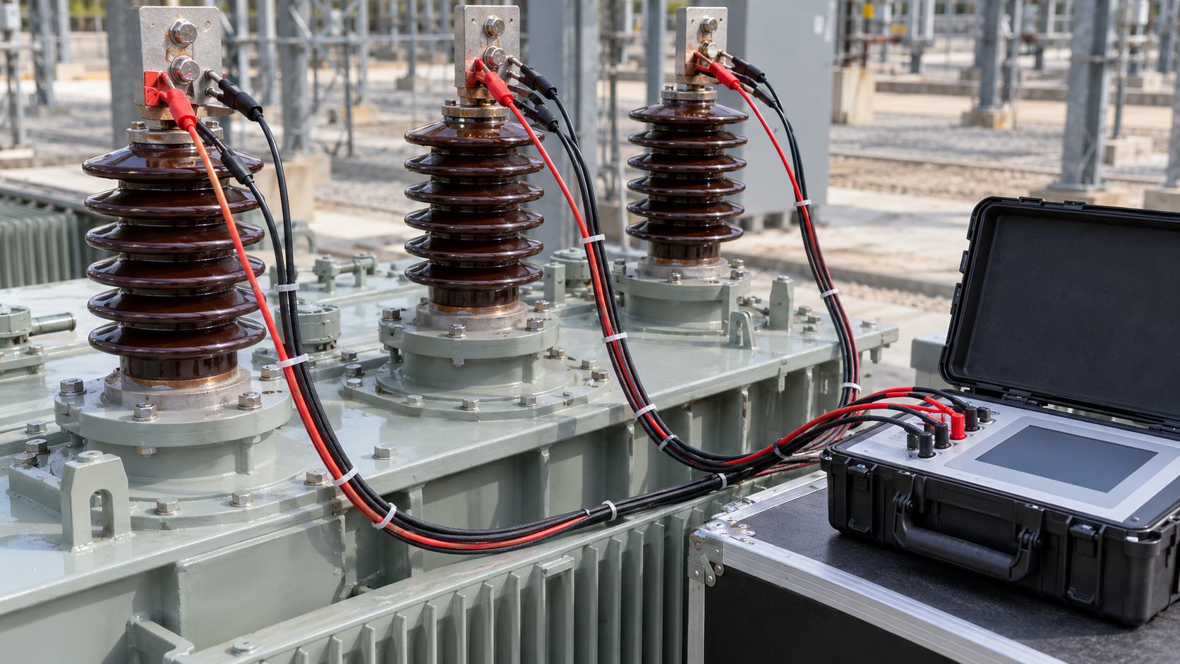
Tap position changes the electrical path and often the number of active turns in the measured circuit. Record the full tap designation, not only a position number: identify whether the device is an off-circuit tap changer or an on-load tap changer, the direction of travel, and the terminal combination. If measurements are required at several positions, follow the manufacturer’s sequence and ensure that the final reported position is unambiguous.
Resistance varies with conductor temperature. For copper or aluminium, a temperature correction may be calculated using the material-specific relation specified by the manufacturer or approved procedure. The conversion must identify the assumed reference temperature and conductor material. Do not mix a correction formula or constant from one material with another, and do not compare an uncorrected site reading with a corrected factory value. If material or reference temperature is uncertain, record the raw value and ask the OEM to define the comparison basis.
Stabilization matters because the instrument reading can drift while current builds in the winding, test leads settle, or temperature changes. Use a declared stability criterion, such as a specified change over a specified observation interval, only if the approved procedure defines it. Capture the time series or instrument export when available, not just the final display. Where readings remain unstable, stop and investigate the connection, test current, instrument range, magnetic settling, or circuit configuration rather than selecting a convenient value.
| Check point | Record before testing | Why it matters | Engineering response if unclear |
|---|---|---|---|
| Transformer identity | Serial number, rating, vector group, winding terminals | Prevents comparing another asset or a different circuit | Stop comparison until nameplate and factory report agree |
| Tap configuration | Full tap label, changer type, terminal sequence | Different positions can produce different resistance paths | Confirm the required position sequence with the OEM |
| Winding temperature | Value, sensor/location, time, method, material basis | Raw resistance changes with conductor temperature | Retain raw data; agree correction basis before comparison |
| Test circuit | Current terminals, sense terminals, lead routing, neutral state | Connection topology and lead resistance affect the result | Use a marked connection sketch and repeat only after correction |
| Instrument and current | Model, serial, calibration, range, test current | Current and measurement method affect stability and resolution | Check OEM guidance and instrument limits |
| Stability and discharge | Stability criterion, time series, discharge confirmation | Winding inductance creates settling time and stored energy | Follow instrument discharge sequence; do not move live leads |
| Comparison basis | Factory report, corrected/raw status, phase definitions | Values are comparable only when measurement bases align | Request OEM review; do not invent a universal tolerance |
Before connecting the test set, compare the planned sequence against the approved method statement and the terminal diagram. Photograph or sketch the connection arrangement for each circuit where the site documentation rules allow it. Connect current and potential leads exactly as specified by the instrument manufacturer; separate current and sense contacts when the test arrangement supports a four-wire measurement, and clean the contact surfaces without damaging coatings or terminal plating.
At each required tap position, record the actual terminal pair and current direction. Allow the reading to stabilize to the agreed criterion, then capture resistance, test current, temperature, elapsed stabilization time, instrument range, and timestamp. If the reading is outside the planned range or unstable, document the condition and investigate before proceeding. Never silently substitute a range, test current, or measurement topology; a method change must be logged and approved.
Where the winding is delta-connected or an individual phase cannot be measured directly, the observed path may combine phase resistances. Use the calculation or comparison method provided by the manufacturer or an approved technical procedure. Do not infer an individual phase value from a composite result without stating the assumptions and equations. The same caution applies to tertiary, regulating, and neutral windings whose terminals or internal connections differ from the main winding.
After the final measurement, complete the test set’s prescribed discharge cycle, verify the winding is safe to disconnect, and only then move leads. Reinstall removed links, neutral connections, cable connections, and covers under the approved work instruction. Record restoration checks, torque records where applicable, and independent verification of the as-left configuration. A correct measurement followed by an incomplete restoration is not acceptable handover evidence.

Compare each site measurement with the appropriate factory test result, prior commissioning baseline, or OEM data. First align the asset and terminal identity, tap position, measurement topology, temperature basis, material assumption, and correction status. A mismatch in one of these items can create a misleading difference. Where practical, compare the phase pattern as well as the absolute values; the phase-to-phase comparison must use the manufacturer’s prescribed method for the winding connection.
Project teams should not impose a generic percentage limit unless it is explicitly present in the governing specification, utility requirement, approved procedure, or OEM instruction. Acceptance criteria may depend on the transformer design, measurement circuit, temperature correction, and test method. If readings differ from the baseline, confirm data transcription, test leads, terminal contact, tap setting, temperature, stability, and instrument configuration before escalating. A repeat test is useful only when the reason for repeating and the changed conditions are documented.
Escalate a persistent unexplained deviation to the transformer manufacturer and the responsible protection or commissioning engineer. Provide raw readings and context rather than only a pass/fail statement. The technical review may call for other diagnostic tests, but these must be selected and approved for the actual asset; winding resistance alone cannot determine whether a transformer can be energized.
The test dossier should make it possible for an independent reviewer to reconstruct what was tested and how. Include the approved method statement revision, permit and isolation record references, transformer nameplate and serial number, winding and terminal sketch, tap positions, test set identification and calibration evidence, test current, raw readings, temperature source, correction formula and reference basis, stabilization evidence, discharge and restoration checks, and names or signatures of the performing and witnessing personnel.
Attach the factory resistance baseline and identify which factory test report pages are being compared. Mark the basis of each comparison: raw or temperature-corrected, winding material assumption, and phase/circuit definition. Record any deviations, repeat readings, instrument warnings, inaccessible terminals, and OEM dispositions. Keep the original instrument export where available; a retyped summary should not replace the source file.

For linked EPC quality records, coordinate this test with the broader transformer installation quality dossier, the site acceptance test checklist, and the factory acceptance witness plan. These records serve different stages: a factory baseline supports comparison, while site records show the installed asset configuration and the field method used.
If oil sampling or other condition checks are part of the project scope, cross-reference the relevant DGA baseline and handover record without treating those results as substitutes for winding resistance. Keep the dossier index consistent with the EPC document numbering and final asset register so that the utility operator can retrieve the record years after commissioning.
The applicable contract documents take precedence for a project-specific test. IEEE C57.152-2013 is a guide for diagnostic field testing of fluid-filled power transformers, regulators, and reactors; use it as guidance within its scope and consult the project’s adopted edition and OEM procedure. IEEE C57.93-2019 addresses installation and maintenance of liquid-immersed power transformers and can inform the broader field process. IEC 60076-1:2011 sets general requirements for power transformers, but it does not replace the detailed test instructions and acceptance criteria for a particular unit. Confirm current editions, amendments, and utility adoption status against procurement specifications before tender or execution.
Each reference has a distinct role. The commissioning engineer should identify which contract requirement is mandatory, which standard is informative guidance, and which manufacturer instruction controls the particular equipment. If sources conflict, stop and obtain a documented technical clarification; do not resolve a contract conflict by assuming that one test guide overrides an approved project requirement.
Check whether the two reports use the same tap position, phase definitions, current and potential lead placement, temperature basis, and correction method. Confirm the factory report value was not transcribed from another winding or a different terminal combination. If all comparison conditions align and the deviation remains, submit both raw data sets to the manufacturer for a written assessment.
Check stable contact pressure, terminal cleanliness, lead placement, test current, range, and the measurement’s settling period. Verify that the winding was not still changing temperature and that the previous test’s discharge sequence was completed. Record the initial and final readings; do not discard outliers without a documented reason.
Use the approved connection and calculation method for the winding configuration. If a result is composite, label it as such. A test sheet that calls a line-to-line path a phase resistance can cause an invalid comparison later.
Do not fill the gap with an arbitrary rule of thumb. Request the limit or evaluation method from the project engineer, owner, utility, or OEM. State the source, document revision, and approval in the test report.
For transformer site commissioning, the test record should remain connected to the actual equipment schedule and factory baseline. Zisheng Electric supports EPC coordination for oil-immersed distribution transformers and high-voltage power transformers, with project interfaces defined by the approved drawings and technical specification.
To plan transformer winding resistance testing, provide the transformer datasheet and nameplate, winding connection and vector group, tap schedule, factory resistance report, approved test procedure, instrument details, temperature method, terminal and grounding arrangements, installation status, and site acceptance requirements. Include the single-line diagram and any utility-specific acceptance documents so the test sequence and reporting basis can be agreed before mobilization. Our engineering team will review the requirements and respond to project inquiries within 24 hours.

Plan substation revenue metering handover with verified CT/VT ratios, register mapping, time conventions and end-to-end data evidence. Define utility acceptance, configuration custody and the records needed for EPC closeout.
View details
Plan substation cable penetration firestopping through an EPC checklist for opening geometry, tested systems, cable supports, inspections and handover evidence. Coordinate transformers and switchgear with Zisheng Electric.
View details
Plan a transformer first-service thermal survey with safe access, representative load records, cooling checks, evidence ownership and clear EPC handover decisions.
View details
A safe EPC guide to the transformer core ground test before energization, including isolation, manufacturer-approved test conditions, records and restoration checks.
View details